Evaporation device and control method for driving components thereof

A driving component and evaporation technology, which is applied in vacuum evaporation plating, sputtering plating, ion implantation plating, etc., can solve problems such as the influence of evaporation film uniformity, and achieve the effect of improving poor uniformity and ensuring uniformity

Active Publication Date: 2021-06-01
TCL CHINA STAR OPTOELECTRONICS TECH CO LTD
View PDF11 Cites 0 Cited by
  • Summary
  • Abstract
  • Description
  • Claims
  • Application Information

AI Technical Summary

Problems solved by technology

[0006] The present application relates to a control method of an evaporation device and its driving components, which is used to solve the problem that the evaporation device in the prior art has an influence on the uniformity of the evaporation film during the evaporation process

Method used


Image

  • Evaporation device and control method for driving components thereof
  • Evaporation device and control method for driving components thereof
  • Evaporation device and control method for driving components thereof

Examples


Embodiment 1

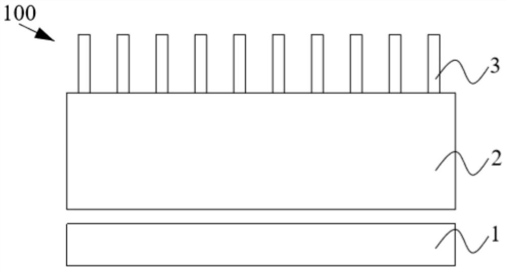
[0043] refer to figure 1 , is a first front view 100 of the evaporation device provided in the embodiment of the present application. It includes: a heating device 1, a crucible 2 and a nozzle 3. The heating device 1 is arranged under the nozzle 3 and the crucible 2, and is used for evaporating and heating the material in the crucible 2; the crucible 2 is a cube or a cylinder, made of organic materials, It is arranged between the heating device 1 and the nozzle 3, and is used to contain evaporation materials; the nozzle 3 is a hollow cylinder, and a plurality of the nozzles 3 are arranged at equal intervals on the crucible 2 away from the The surface of the heating device, and the nozzle 3 is perpendicular to the crucible 2, that is, the preset angle is 90 degrees. When the preset angle is 90 degrees, the uniformity of the vapor-deposited thin film layer of the nozzle is the best when the nozzle is vapor-deposited, and the area covered by the vapor-deposition area is the lar...

Embodiment 2

[0052] refer to Figure 9 , is a second front view 900 of the evaporation device provided in the embodiment of the present application. Including: heating device 1', crucible 2' and nozzle 3'. The heating device 1' is arranged under the nozzle 3' and the crucible 2', and is used for evaporating and heating the material in the crucible 2'; the crucible 2' is a cube or a cylinder. Made of organic materials, set between the heating device 1' and the nozzle 3', used to hold the evaporation material; the nozzle 3' is a hollow cylinder, and a plurality of the nozzles 3' are equally spaced Set on the crucible 2', the difference from the first embodiment is that the preset angle between the nozzle 3' and the crucible 2' can be not only 90 degrees, but also 75 degrees, 80 degrees or 85 degrees. As the preset angle gradually decreases, the area covered by the vapor deposition area also gradually decreases. In combination with the baffle plate or the cover on the nozzle, the opening ...


PUM


Abstract

An evaporation device, comprising: a heating device, a crucible, and a plurality of nozzles; wherein, the heating device is arranged under the crucible, and performs evaporation and heating on the crucible; the crucible is arranged on the heating device Between the nozzle and the nozzle, it is used to hold the evaporation material; a plurality of the nozzles are equidistantly arranged on the upper surface of the crucible; its beneficial effects include: first, by setting the nozzles in the evaporation device to equal The spacing arrangement improves the problem of poor uniformity of the vapor deposition device when vapor deposition; secondly, through the control of the baffle plate on the nozzle, the uniformity of the vapor deposition film is further ensured.

Description

technical field [0001] The present application relates to the field of display, in particular to a method for controlling an evaporation device and a driving component thereof. Background technique [0002] Organic Light-Emitting Diode (OLED) devices have the characteristics of self-illumination, wide viewing angle, high contrast, fast response, light and thin, etc., and have become the main trend of display technology. [0003] At present, OLED devices used in small and medium-sized OLED display panels such as mobile phone screens and computer screens are mainly produced by vacuum thermal evaporation. The evaporation process is to heat the evaporation material under certain vacuum conditions, so that the evaporation material melts (or sublimates) into a vapor composed of atoms, molecules or atomic groups, and then condenses on the surface of the substrate to form a film, thereby forming the functional layer of the OLED device. [0004] In the evaporation process, there are...

Claims


Application Information

Patent Timeline
Patent Type & Authority Patents(China)
IPC IPC(8): C23C14/24C23C14/54
CPCC23C14/24C23C14/542
Inventor 汪国杰
Owner TCL CHINA STAR OPTOELECTRONICS TECH CO LTD
Why Eureka
Try Eureka