Multi-functional mixed transportation pump

A mixed-infusion pump and multi-functional technology, applied in the field of multi-functional mixed-infusion pumps, can solve the problems of easy air lock, high medium state requirements, poor power output stability, etc., to improve reliability and stability, and operation adaptability Strong, de-blocking effect

Pending Publication Date: 2019-08-09
SHENGLI OIL FIELD HIGHLAND GASOLINEEUM EQUIP
View PDF0 Cites 0 Cited by
  • Summary
  • Abstract
  • Description
  • Claims
  • Application Information

AI Technical Summary

Problems solved by technology

[0003] ①When the multi-phase liquid to be transported contains a large proportion of gas, it is easy to cause air lock, so that the pump cannot work;
[0004] ② When transporting high-viscosity media or media containing solid particles, the pump efficiency is low, and even affected by high viscosity, the pump cannot work effectively;
[0005] ③ It is not suitable for harsh working conditions, and the performance of the pump is seriously reduced when the medium c

Method used


Image

  • Multi-functional mixed transportation pump
  • Multi-functional mixed transportation pump
  • Multi-functional mixed transportation pump

Examples


Embodiment 1

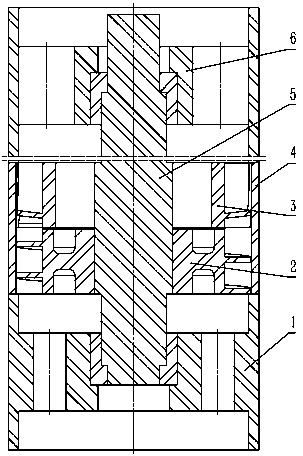
[0040] refer to Figure 1 to Figure 4 As shown, a multifunctional mixed pump includes a pump barrel 4 , a pump shaft 5 , a suction head 1 and a discharge head 6 .

[0041] The lower end of the pump barrel 4 is connected to the suction head 1, and the upper end of the pump barrel 4 is connected to the discharge head 6. The cavity of the pump barrel 4 is provided with a guide wheel 3 and an impeller 2 sequentially from top to bottom. end contact.

[0042] The suction head 1, the discharge head 6, the impeller 2 and the guide wheel 3 are all provided with shaft holes adapted to the pump shaft 5, and the shaft holes on the suction head 1, the discharge head 6, the impeller 2 and the guide wheel 3 are all aligned with the pump shaft. The cylinder 4 is located on the same axis, and the pump shaft 5 passes through the cavity of the pump cylinder 4 along the axis of the pump cylinder 4, and passes through the shaft holes of the suction head 1, the guide wheel 3, the impeller 2 and th...

Embodiment 2

[0055]In this embodiment, on the basis of Embodiment 1, the combination of one impeller 2 and one guide wheel 3 is set as a set of power mechanisms, and multiple sets of power mechanisms are stacked and assembled on the pump shaft 5 .

[0056] During assembly: the upper end surface of the impeller 2 in the same group of power mechanisms is in contact with the lower end surface of the adjacent guide wheel 3, and the upper end surface of one set of guide wheels 3 in the adjacent two sets of power mechanisms is in contact with the lower section of the other set of impeller 2, It can be realized by repeated superposition. According to the difference of the output power of the pump, the height of the pump barrel 4 can be increased to install a power mechanism combining the 1-700-stage impeller 2 and the guide wheel 3, and drive multiple sets of power through a single pump shaft 5. The impeller 2 in the mechanism rotates, so that the present invention has the characteristics of high ...

Embodiment 3

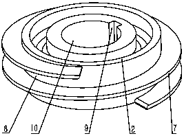
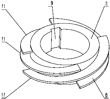
[0060] In this embodiment, on the basis of Embodiment 1, the number of longitudinal guide vanes 12 arranged on the outer circumference of the guide wheel 3 is specifically 4-20 pieces, and the guide vanes 12 are equally spaced around the outer circumference of the guide wheel 3;

[0061] The guide vane 12 presents a curved surface that smoothly transitions from a curved section to a straight section from the guide inlet end 14 to the guide outlet end 15, and the curved surface faces the direction of the outlet of the spiral flow channel 8, thereby facilitating the flow direction of the fluid and making it easier for the fluid to leave the spiral flow channel 8 and then directly into the longitudinal fluid passage 13.


PUM


Abstract

The invention relates to the technical field of petroleum mechanical equipment, and particularly discloses a multi-functional mixed transportation pump. The multi-functional mixed transportation pumpis characterized in that the multi-functional mixed transportation pump includes a pump cylinder, a pump shaft, a sucking head and a discharging head, wherein the lower end of the pump cylinder is connected with the sucking head, the upper end of the pump cylinder is connected with the discharging head, a pump cylinder cavity is internally and sequentially provided with a guide wheel and an impeller from the top to the bottom, the lower end surface of the guide wheel is attached to the lower end surface of the impeller, shaft holes matched with the pump shaft are correspondingly formed in thesucking head, the discharging head, the impeller and the guide wheel, the pump shaft penetrates in the pump cylinder cavity along the axial line of the pump cylinder, and penetrates through the shaftholes of the sucking head, the guide wheel, the impeller and the discharging head, the pump shaft is fixedly connected with the impeller, and moving gaps are correspondingly reserved between the shaftholes of the sucking head, the guide wheel and the discharging head and the shaft. The multi-functional mixed transportation pump has the function of multiphase flow or mixed transportation of high viscosity liquid, liquid mediums with high viscosity, high temperature, high solid content or rich in gas can be better transported, phenomena of blocking, cavitation erosion and gas locking are eliminated to maximum extent, and the multi-functional mixed transportation pump has the characteristics that operational adaptation is high, reliability is high, the pump efficiency is high, and energy saving is achieved.

Description

technical field [0001] The invention relates to the technical field of petroleum machinery equipment, in particular to a multifunctional mixed transportation pump. Background technique [0002] At present, crude oil transportation uses submersible pump as the power mechanism. The existing submersible pump is a multi-stage centrifugal pump structure, which is mainly composed of impeller, guide casing, pump shaft, pump casing and upper and lower joints, etc., which has made contributions to mixed oil production. , but it also has the following shortcomings or deficiencies: [0003] ①When the multi-phase liquid to be transported contains a large proportion of gas, it is easy to cause air lock, so that the pump cannot work; [0004] ② When transporting high-viscosity media or media containing solid particles, the pump efficiency is low, and even affected by high viscosity, the pump cannot work effectively; [0005] ③ It is not suitable for harsh working conditions, and the per...

Claims


Application Information

Patent Timeline
IPC IPC(8): F04D7/04F04D7/06F04D1/06F04D29/22F04D29/24F04D29/42F04D29/66
CPCF04D7/04F04D7/06F04D1/06F04D29/2222F04D29/2216F04D29/225F04D29/242F04D29/426F04D29/185F04D29/669
Inventor 杨献平潜凌程鹏韩涛
Owner SHENGLI OIL FIELD HIGHLAND GASOLINEEUM EQUIP
Why Eureka
Try Eureka