
Electric drive fan shafting reforming system

A technology of fan shaft and secondary fan, applied in the direction of mechanical equipment, machine/engine, liquid fuel engine, etc., can solve the problems of throttling loss, high-quality energy waste, etc., and achieve the effect of saving economic wealth and improving resource utilization

Pending Publication Date: 2019-08-09
HARBIN GUANGHAN POWER TRANSMISSION +1
View PDF0 Cites 0 Cited by
  • Summary
  • Abstract
  • Description
  • Claims
  • Application Information

AI Technical Summary

Problems solved by technology

[0003] The present invention aims to solve the problem that high-quality energy is wasted due to large throttling losses caused by steam in the process of temperature and pressure reduction

Method used


Image

  • Electric drive fan shafting reforming system
  • Electric drive fan shafting reforming system

Examples


specific Embodiment approach 1

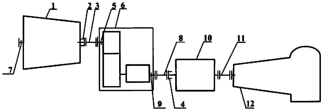
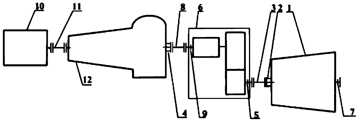
[0014] Specific implementation mode one: refer to figure 1 This embodiment will be described in detail. An electric drive fan shaft transformation system described in this embodiment includes a double-shaft extension motor 10, a coupling C11 and a primary fan 12. One end of the output shaft of the double-shaft extension motor 10 passes through The coupling C11 is connected with the input shaft of the primary fan 12, and it is characterized in that it also includes a rear back pressure machine 1, a flange A2, a coupling A3, a flange B4, a thrust bearing A5, a transmission clutch 6, Coupling B8 and thrust bearing B9;

[0015] The flange A2 is installed on the output shaft of the rear back pressure machine 1, and the flange A2 is connected with the input shaft of the transmission clutch 6 through the coupling A3. The input shaft of the transmission clutch 6 is equipped with a thrust bearing A5, and the thrust bearing A5 is set inside the speed change clutch 6, the output shaft o...

specific Embodiment approach 2

[0018] Specific embodiment 2: This embodiment is to further limit the shafting transformation system of an electric drive fan described in the specific embodiment 1. In this embodiment, the non-output end of the rear back pressure machine 1 is provided with a thrust bearing C7 , and the thrust bearing C7 is arranged inside the back press machine 1, and the other composition and connection methods are the same as those in the first embodiment.

[0019] The function and arrangement reason of the thrust bearing C7 mentioned in this embodiment are the same as those of the thrust bearing A5 and the thrust bearing B9, mainly for the purpose of axially limiting the output shaft in the rear back press 1 to a certain extent.

specific Embodiment approach 3

[0020] Specific embodiment 3: This embodiment is to further limit the electric drive fan shaft transformation system described in specific embodiment 1. In this embodiment, the coupling A3, coupling B8 and coupling C11 is a diaphragm coupling, and the other components and connection methods are the same as those in Embodiment 1.

[0021] Coupling A3, coupling B8 and coupling C11 mentioned in this embodiment are all used to absorb the thermal expansion of the rotor during the operation of the equipment, to compensate for certain axial movement, and to avoid axial load When the rotor produces axial movement.


PUM


Abstract

The invention relates to an electric drive fan shafting reforming system, and relates to the field of industrial steam supplying and energy conservation in thermal power plants. The electric drive fanshafting reforming system aims to solve the problem of high-quality energy waste caused by large throttling loss produced in the process of temperature reduction and pressure reduction of steam. According to the electric drive fan shafting reforming system, on the basis of an original electromotor and a primary fan, a variable speed clutch and a rear back press are additionally arranged, an original drive mode which can only be driven by the electromotor is changed, and thus gas generated by the steam in the process of temperature reduction and pressure reduction can be used as a power sourceof the primary fan, the electric drive fan shafting reforming system is mainly used for driving fans in industry, and meanwhile, the high-quality energy lost by the large throttling loss in the process of temperature reduction and pressure reduction of the steam is recovered and utilized.

Description

technical field [0001] The invention relates to a system for reforming the shaft system of an electric drive fan. The utility model belongs to the field of industrial steam supply and energy saving. Background technique [0002] The external steam supply of the thermal power plant adopts cold re-steam and hot re-steam for industrial steam. The cold re-steam has a pressure of about 4MPa and a temperature of 330-350°C under rated working conditions. The parameters required by the user to be transferred to heat through a desuperheating and decompression station are: pressure 1.4MPa, temperature 200-240°C. Due to the extreme mismatch between the parameters of the steam extraction port and the parameters of industrial steam, the steam has a large throttling loss in the process of reducing temperature and pressure. If things go on like this, it will not only waste high-quality energy, but also indirectly cause certain economic losses. Contents of the invention [0003] The in...

Claims


Application Information

Patent Timeline
Patent Type & Authority Applications(China)
IPC IPC(8): F04D25/06F04D29/054F01D15/10
CPCF04D25/06F04D29/054F01D15/10
Inventor 仇实王勇帆罗萌周金阳曾德龙邓广琳朱振荣王琦徐巍
Owner HARBIN GUANGHAN POWER TRANSMISSION
Learn More