Static loading device and method for anti-slip test of inclined supporting joint

A technology of static loading and oblique support, applied in measuring devices, using stable tension/pressure to test the strength of materials, instruments, etc., can solve the problems of cumbersome operation, inability to automatically balance, inconvenient installation, etc., and meet the requirements of test conditions Low cost, low production cost and high reliability

CN110108562APending Publication Date: 2019-08-09XI'AN UNIVERSITY OF ARCHITECTURE AND TECHNOLOGY
0 Cites 3 Cited by

Patent Information

Authority / Receiving Office
CN · China
Patent Type
Applications(China)
Current Assignee / Owner
Publication Date
2019-08-09

Smart Images

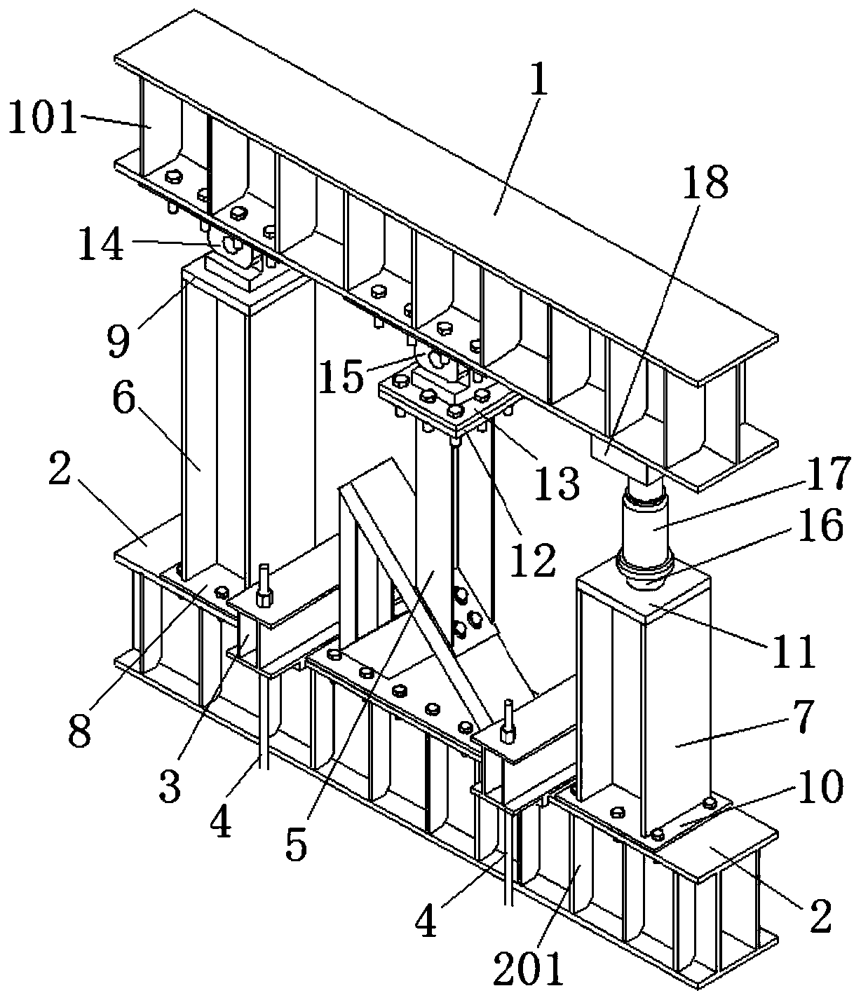
  • Figure 1
    Figure 1
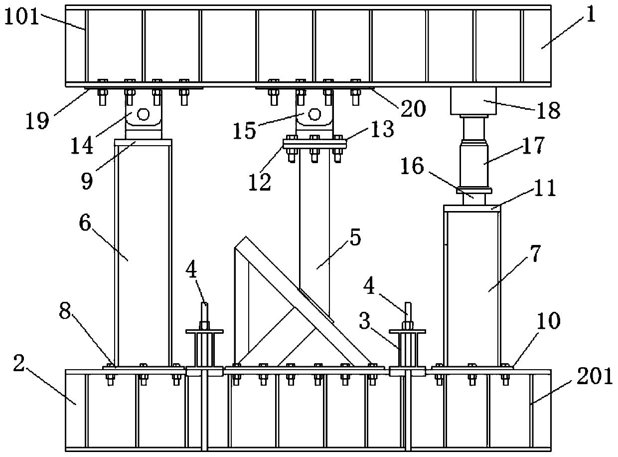
  • Figure 2
    Figure 2
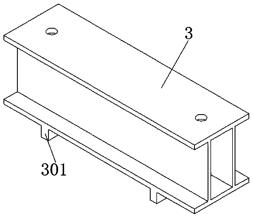
  • Figure 3
    Figure 3
Patent Text Reader

Abstract

The invention discloses a static loading device and method for an anti-slip test of an inclined supporting joint. A ground beam is horizontally and fixedly arranged on a test bed, counterforce beams are arranged on the upper part of the ground beam in parallel, and a first side column and a second side column are arranged between the counterforce beams and the ground beam in parallel; the upper end of the first side column is hinged to one end of the counterforce beams, the lower end of the second side column is fixedly connected with the other end of the ground beam, a pressure gauge is arranged between the second side column and a jack, and the upper end of the jack tightly abuts against the other end of the counterforce beams; the lower part of an inclined supporting joint test piece isconnected with the ground beam, and the upper part of the inclined supporting joint test piece is hinged to the counterforce beams; a hinged rotation center between the inclined supporting joint testpiece and the counterforce beams, a hinged rotation center between the first side column and the counterforce beams and the top surface position of the jack are arranged in line. The static loading device is low in manufacturing cost, high in reliability, simple to install, capable of achieving self-balance, simple in operation method in the static loading process, and low in test condition requirement.
Need to check novelty before this filing date? Find Prior Art

Description

technical field

[0001] The invention belongs to the technical field of load test loading, in particular to a static loading device and a loading method for an anti-slip test of a diagonal support node. Background technique

[0002] As a key part of the prefabricated steel structure building, the node plays a key role in the installation and use stage of the prefabricated building. With the continuous updating of prefabricated steel structure building forms, the connection forms of nodes are also constantly enriched and developed. However, the existing loading devices for testing the mechanical properties of nodes show certain limitations, such as the high price of servo loading devices, complex functions, and difficult operation. The shortcomings of cumbersome, bulky, inconvenient installation, and inability to automatically balance make the node test subject to various restrictions. Contents of the invention

[0003] Aiming at the technical problems existing in the prior...

Examples

Embodiment Construction

[0031] The following will clearly and completely describe the technical solutions in the embodiments of the present invention with reference to the accompanying drawings in the embodiments of the present invention. Obviously, the described embodiments are only some, not all, embodiments of the present invention. Based on the embodiments of the present invention, all other embodiments obtained by persons of ordinary skill in the art without making creative efforts belong to the protection scope of the present invention.

[0032] A static loading device for the anti-slip test of a diagonally supported node, comprising a reaction beam 1, a ground beam 2, a first side column 6, a second side column 7, a pressure gauge 16, and a jack 17; the ground beam 2 is horizontally fixed on the On the test bench, the reaction beam 1 is arranged in parallel on the upper part of the ground beam 2, and the first side column 6 and the second side column 7 are arranged in parallel between the react...