New energy automobile motor test board

A new energy vehicle and motor testing technology, applied in the direction of motor generator testing, etc., can solve problems such as drive motor output shaft jumping, and achieve the effect of improving stability

Inactive Publication Date: 2019-08-09
重庆理工清研凌创测控科技有限公司
View PDF13 Cites 7 Cited by
  • Summary
  • Abstract
  • Description
  • Claims
  • Application Information

AI Technical Summary

Problems solved by technology

[0006] In view of the above-mentioned deficiencies existing in the prior art, the purpose of the present invention is to solve the stalling phenomenon that occurs during the operation of the tested generator in the prior art, and the prob

Method used


Image

  • New energy automobile motor test board
  • New energy automobile motor test board
  • New energy automobile motor test board

Examples


Embodiment 1

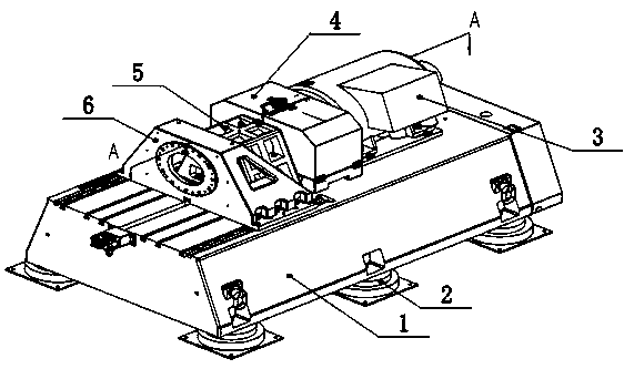
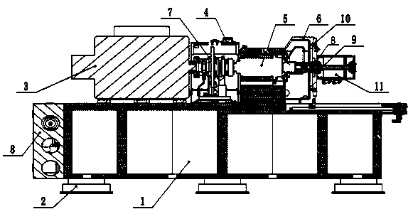
[0042] Example 1: see figure 1 with figure 2 , New energy vehicle motor test bench, including workbench 1 and valve box 8 set on workbench 1, dynamometer 3 set on workbench 1, dynamometer 3 is provided with an output shaft inside, and the output shaft is connected There is a motor shaft 9 to be tested, and the motor shaft 9 is connected with a new energy motor 11; there is a drive device for driving the dynamometer 3 and the new energy motor 11. When the drive device drives the dynamometer 3, the new energy motor 11 generates power. When the device drives the new energy motor 11, the dynamometer 3 generates electricity; it also includes a locked-rotor mechanism 7 that prevents the output shaft from rotating. A shield 4 is provided outside the locked-rotor mechanism 7 to prevent the locked-rotor mechanism 7 from getting wet. One side of the locked-rotor mechanism 7 is coaxially connected with the dynamometer 3, and the other side of the locked-rotor mechanism 7 is connected with...

Embodiment 2

[0046] Example 2: see Figure 4 The basic structure of the second embodiment is the same as that of the first embodiment. The difference is that the locked-rotor mechanism 7 includes a hydraulic device and a locked-rotor disk 17, and the locked-rotor disk 17 is embedded with an adapter disk 18 fixed on the output shaft, and the adapter disk 18 is used to test the torque of the output shaft. The two sides of the locked turntable 17 are respectively provided with brakes 16 for clamping both sides of the locked turntable 17, and the brakes 16 are driven by hydraulic devices. A hydraulic pipe 19 is provided on the hydraulic device, and the hydraulic pipe 19 is connected to the input end of the brake 16. The hydraulic pipe 19 transmits a pressure source to the brake 16 so that the brake 16 locks the blocking disk 17.

[0047] Before starting the locked-rotor test, the brake 16 is driven by a hydraulic device. Then, the brake 16 locks the locked-rotor disc 17 and starts the locked-roto...

Embodiment 3

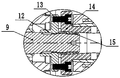
[0048] Example 3: See image 3 with Figure 5 The basic structure of the third embodiment is the same as that of the first embodiment, the difference is that the spline expansion sleeve structure includes an inner ring 12 and an outer ring 14 arranged from the inside to the outside. The inner wall of the inner ring 12 and the outer wall of the spline adapter shaft For spline connection, the outer ring 14 is arranged in the bearing housing 5, and a coupling plate 10 is arranged in the bearing housing 5 for fixing the output shaft. The inner ring 12 includes an inner ring flange 20 and one side thereof is fixedly connected with an inner ring cone 22. The inner ring flange 20 is provided with a number of inner ring mounting holes; the outer ring 14 includes an outer ring flange and one side fixed The outer ring cone is connected, and the outer ring flange is provided with a number of outer ring mounting holes; the inner ring mounting holes and outer ring mounting holes are both th...


PUM


Abstract

The invention discloses a new energy automobile motor test board, comprising a workbench, a dynamometer, a driving device as well as a rotor locking mechanism and a spline expanding and clamping sheath structure, wherein the dynamometer is arranged on the workbench, an output shaft is arranged inside the dynamometer, the output shaft is connected with a to-be-tested motor shaft, and the motor shaft is connected with a new energy motor; the driving device is in charge of driving the dynamometer and the new energy motor, when the driving device drives the dynamometer, the new energy motor generates electricity, and when the driving device drives the new energy motor, the dynamometer generates electricity; the rotor locking mechanism is in charge of preventing the output shaft from rotating,one side of the rotor locking mechanism is coaxially connected with the dynamometer, and the other side of the rotor locking mechanism is connected with a bearing block; and the spline expanding and clamping sheath structure is in charge of flexibly connecting the output shaft with the motor shaft, one side of the spline expanding and clamping sheath structure is connected with the bearing block,and the other side of the spline expanding and clamping sheath structure is connected with the motor shaft directly or is connected with the motor shaft by virtue of a spline adapter shaft of a hollowstructure. The new energy automobile motor test board disclosed by the invention can perform a multi-angle locked-rotor test on the locked-rotor phenomenon of a tested motor and also can prevent themotor shaft from running out.

Description

Technical field [0001] The invention relates to the technical field of motor testing, in particular to a new energy vehicle motor test bench. Background technique [0002] With the continuous progress of society and the continuous development of science and technology, energy and environmental protection issues have been paid more and more attention by the society. The most important and urgent issue is the energy issue. However, to solve the energy issue fundamentally, in addition to looking for New energy, energy saving is the key, and it is currently the most direct and effective important measure. [0003] At present, the test benches used to test new energy generators on the market basically use pure resistance or inductive loads to directly consume the electrical energy generated by the generator, which will cause all the electrical energy generated by the generator to be wasted. The longer the big test, the more energy was wasted, which would cause a huge waste of energy, w...

Claims


Application Information

Patent Timeline
IPC IPC(8): G01R31/34
CPCG01R31/34
Inventor 张松兰家水刘清泉周鹏任顺政
Owner 重庆理工清研凌创测控科技有限公司
Why Eureka
Try Eureka