Spray cooling type cold plate

A spray cooling and cold plate technology, which is applied to electrical components, electrical solid devices, circuits, etc., can solve the problems of insufficient volume, adaptability and versatility of coverage, and inability to meet the heat dissipation requirements of thermal control systems. Achieve the effect of large spray coverage, small space and reasonable liquid coverage

Inactive Publication Date: 2019-08-09
CHINA ELECTRONIC TECH GRP CORP NO 38 RES INST
View PDF8 Cites 2 Cited by
  • Summary
  • Abstract
  • Description
  • Claims
  • Application Information

AI Technical Summary

Problems solved by technology

At present, there are many researches on the cooling medium, structural strengthening, material and process innovation of the cold plate, but the research on its combination with spray cooling technology is still

Method used


Image

  • Spray cooling type cold plate
  • Spray cooling type cold plate
  • Spray cooling type cold plate

Examples


Embodiment Construction

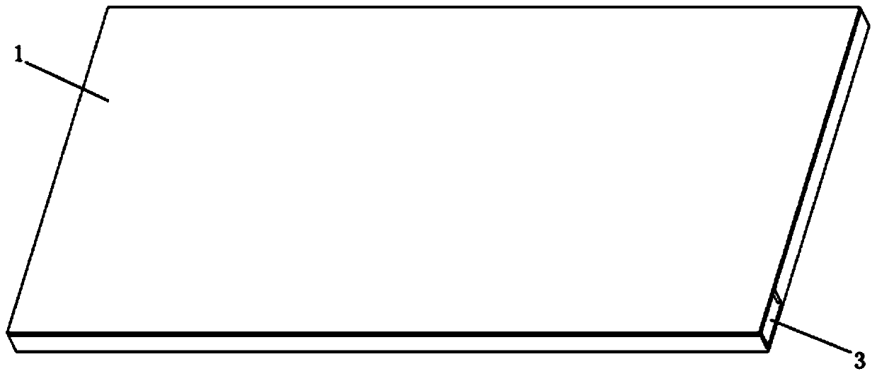
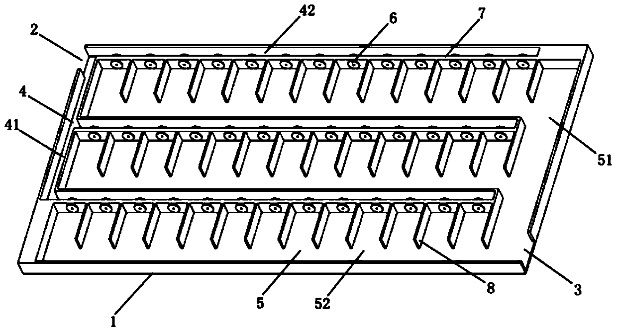
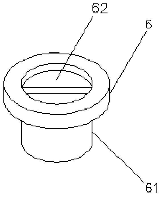
[0031] like Figure 1-3 As shown, the spray-cooled cold plate includes a cold plate shell 1 , a liquid inlet 2 , a liquid discharge 3 , a liquid separation chamber 4 , an atomization chamber 5 , an atomization nozzle 6 , a separator 7 , and fins 8 .

[0032] The cold plate shell 1 is a cuboid hollow thin plate shell with an external dimension of 300mm×150mm×10mm, and its cooling surface is the liquid coverage area on two surfaces of 300mm×150mm; Liquid port 2, liquid discharge port 3, the inner cavity of the cold plate housing 1 is divided into a liquid chamber 4 and an atomization chamber 5 by a partition 7, and the partition 7 is a whole and is connected with the side plate of the cold plate housing 1. One structure.

[0033] The liquid separation chamber 4 includes a liquid inlet flow channel 41 and a liquid separation flow channel 42; the linear liquid inlet flow channel 41 is located on the side of the liquid inlet 2 in the cold plate housing 1 and is parallel to the sid...


PUM


Abstract

The invention discloses a spray cooling type cold plate and relates to the technical field of cooling. The spray cooling type cold plate comprises a cold plate shell, a liquid inlet port, a liquid discharge port, a liquid separation chamber, an atomization chamber and an atomization nozzle. The cold plate shell is a hollow shell and is provided with the liquid inlet port and the liquid discharge port, and the inner cavity of the cold plate shell is separated into the liquid separation chamber and the atomization chamber. The liquid separation chamber communicates with the liquid inlet port, and the atomization chamber communicates with the liquid discharge port. The atomization nozzle is installed between the liquid separation chamber and the atomization chamber, an inlet of the atomization nozzle faces the liquid separation chamber, and an outlet faces the atomization chamber and communicates with the liquid separation chamber and the atomization chamber through the atomization nozzle. The spray cooling type cold plate has the advantages that the liquid cooling plate technology and the spray cooling technology are combined, the applicability is high, and the heat dissipation performance is good.

Description

technical field [0001] The invention relates to the technical field of cooling, in particular to a spray cooling cold plate. Background technique [0002] With the rapid development of electronic devices in the direction of miniaturization, miniaturization and integration, their power density and calorific value also increase, and the ensuing heat accumulation and temperature increase negatively affect the reliability and stability of electronic devices. Therefore, achieving efficient heat dissipation in a compact space has become a key bottleneck restricting the development of high-power electronic devices. [0003] Spray cooling is an emerging high heat flux heat dissipation technology. Compared with traditional cooling technologies, it has the advantages of strong heat dissipation, low contact thermal resistance, and small demand for working fluid. According to the existing public information, spray cooling has achieved 1200W / The heat dissipation performance above cm2 h...

Claims


Application Information

Patent Timeline
IPC IPC(8): H01L23/367H01L23/473
CPCH01L23/367H01L23/3672H01L23/4735
Inventor 章玮玮叶锐王志海赵莲晋鲍睿
Owner CHINA ELECTRONIC TECH GRP CORP NO 38 RES INST
Why Eureka
Try Eureka