Wireless charging device with an adjustable charging area and method thereof

A wireless charging and charging area technology, which is applied to battery circuit devices, circuit devices, current collectors, etc., can solve problems such as reduced transmission efficiency, failure to charge, misalignment of transceiver coils, etc., to improve anti-offset capability, increase charging area, The effect of ensuring stability

Pending Publication Date: 2019-08-09
NORTHWESTERN POLYTECHNICAL UNIV
View PDF7 Cites 9 Cited by
  • Summary
  • Abstract
  • Description
  • Claims
  • Application Information

AI Technical Summary

Problems solved by technology

[0005] In order to avoid the deficiencies of the prior art, the present invention proposes a wireless charging device with adjustable charging area and its method, which solves the problem that the t

Method used


Image

  • Wireless charging device with an adjustable charging area and method thereof
  • Wireless charging device with an adjustable charging area and method thereof
  • Wireless charging device with an adjustable charging area and method thereof

Examples


Embodiment Construction

[0038] The embodiments described below by referring to the figures are exemplary and are intended to explain the present invention and should not be construed as limiting the present invention.

[0039] In describing the present invention, it should be understood that the terms "center", "longitudinal", "transverse", "length", "width", "thickness", "upper", "lower", "front", " Orientation indicated by rear, left, right, vertical, horizontal, top, bottom, inside, outside, clockwise, counterclockwise, etc. The positional relationship is based on the orientation or positional relationship shown in the drawings, which is only for the convenience of describing the present invention and simplifying the description, rather than indicating or implying that the referred device or element must have a specific orientation, be constructed and operated in a specific orientation, Therefore, it should not be construed as limiting the invention.

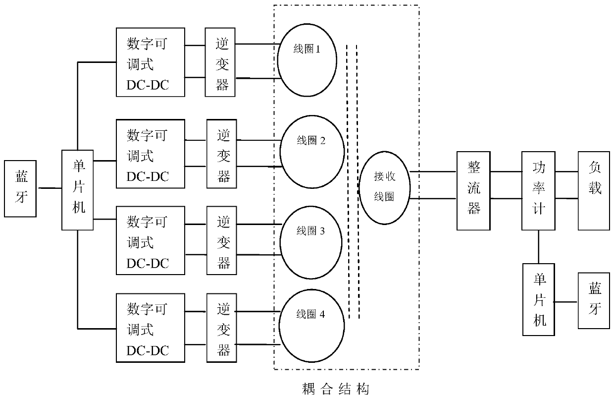
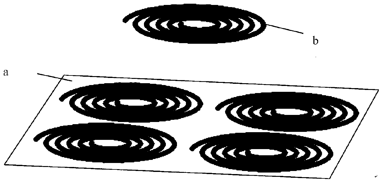
[0040] The invention relates to a wireless c...


PUM


Abstract

The invention relates to a wireless charging device with an adjustable charging area and a method thereof. Based on an array antenna, a multi-coil transmitting and single-coil receiving model, by using a parallel magnetic coupling resonant principle and adjusting an input voltage of a unit in an transmitting coil array, changes the charging area. The wireless charging device is suitable for wireless charging in the fields of mobile phones, UAVs, and electric vehicles. Different from a traditional single-coil model, the wireless charging device has a long transmission distance, a good anti-offset capability and high transmission efficiency, is beneficial to the application in a wireless energy transmission system and greatly improves user experience.

Description

technical field [0001] The invention belongs to the field of wireless charging, and in particular relates to a wireless charging device with an adjustable charging area and a method thereof. Background technique [0002] The discovery of electricity has greatly changed people's lives, and it can be said that we can never do without it. But since the use of electricity, wires have been with us all the time, and wires all over the space or table have brought us a lot of trouble. Whether we can make our surrounding environment more tidy and make our electrical equipment work normally without using wires has become our dream. Therefore, the wireless power transmission technology (Wireless Power Transmission, WPT) emerges at the historic moment under such a background. Wireless power transfer technology has very attractive prospects. For example, it can charge implanted devices in the human body outside the body, saving patients from the pain of replacing batteries through sur...

Claims


Application Information

Patent Timeline
IPC IPC(8): H02J50/40H02J50/90H02J50/80H02J50/10H02J50/12H02J7/00
CPCH02J7/025H02J50/40H02J50/90H02J50/80H02J50/10H02J50/12
Inventor 谢育锋丁君宋琳张毅韬王尧
Owner NORTHWESTERN POLYTECHNICAL UNIV
Why Eureka
Try Eureka