
Current detection circuit of resonant converter and control method thereof

A technology of current detection circuit and resonant converter, applied in the direction of converting DC power input to DC power output, control/regulation system, instrument, etc., can solve the problem that the average current of the resonant converter cannot be obtained, the current control effect is poor, and the cut-off frequency lower problem

Active Publication Date: 2019-08-09
NANJING UNIV OF AERONAUTICS & ASTRONAUTICS
View PDF6 Cites 2 Cited by
  • Summary
  • Abstract
  • Description
  • Claims
  • Application Information

AI Technical Summary

Problems solved by technology

[0004] Although the application of the current loop improves the performance of the LLC resonant converter, it is well known that the current waveform of the resonant converter is not regular and changes with the change of operating conditions, so it cannot be obtained by simply detecting the peak or instantaneous value. The average current of the resonant converter, so the low-pass filter is mostly used in the prior art to filter the induced voltage signal generated by the irregular current signal to obtain the average value information, as described in the US invention patent with the announcement number US8541997B2
The low-pass filter used in this case usually has a very low cut-off frequency. If a low-pass filter is used in the added current loop to obtain the average current information of the resonant converter, the bandwidth of the current loop is limited, and the current control effect is poor. When the dynamic process is severe, the converter may still have a large inrush current in the resonant cavity, which reduces the dynamic performance of the converter

Method used


Image

  • Current detection circuit of resonant converter and control method thereof
  • Current detection circuit of resonant converter and control method thereof
  • Current detection circuit of resonant converter and control method thereof

Examples


Embodiment Construction

[0018] The method of the present invention will be described in detail below with reference to the accompanying drawings. In the following embodiments, many detailed descriptions are only for better understanding of the present application, but for those skilled in the art, they can easily realize that some of the features can be omitted under different circumstances or can be replaced by other elements and methods. In some cases, some operations or contents related to the application are not shown or described in the description, this is to avoid the core part of the application from being overwhelmed by too many descriptions, because for those skilled in the art, It is not necessary to describe these related operations in detail, and they can fully understand the related operations according to the description in the specification and general technical knowledge in the field. In addition, the characteristics, operations or characteristics described in the specification can ...


PUM


Abstract

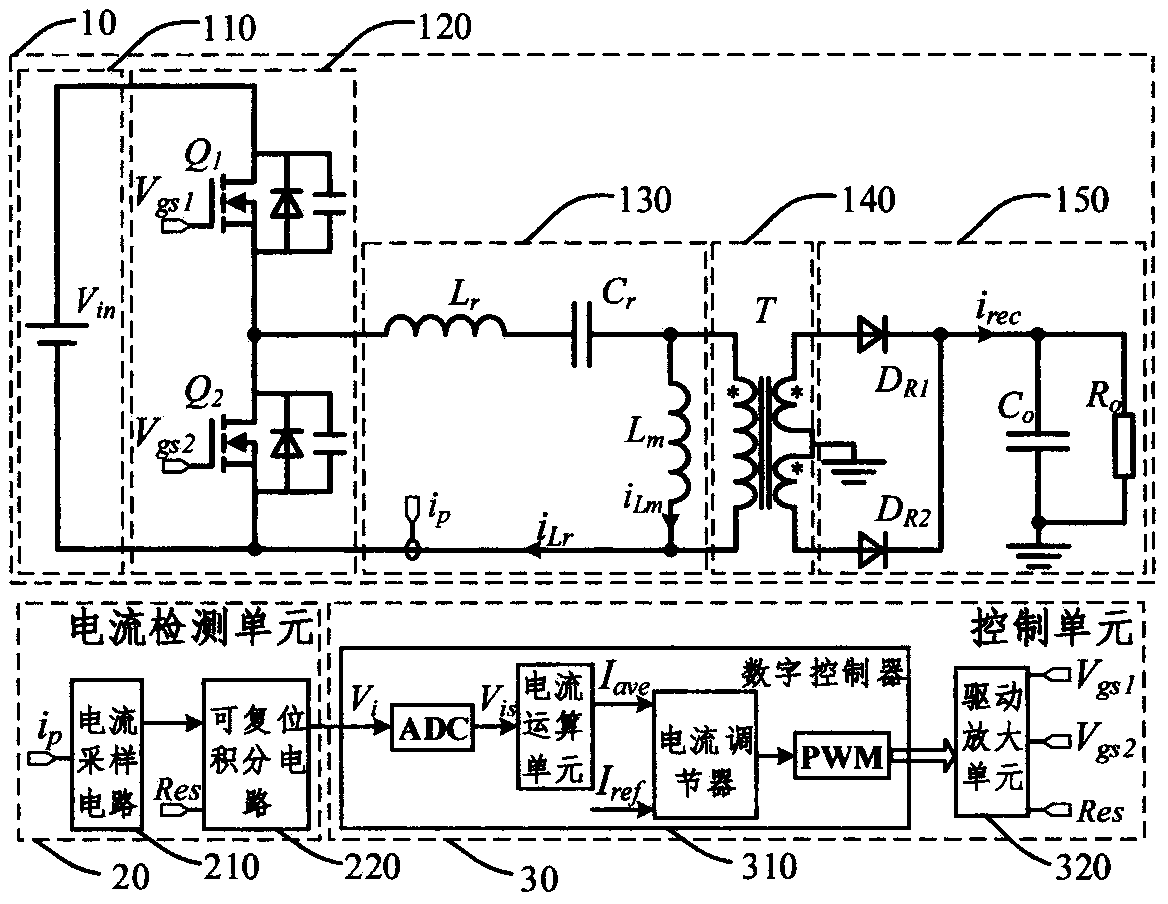
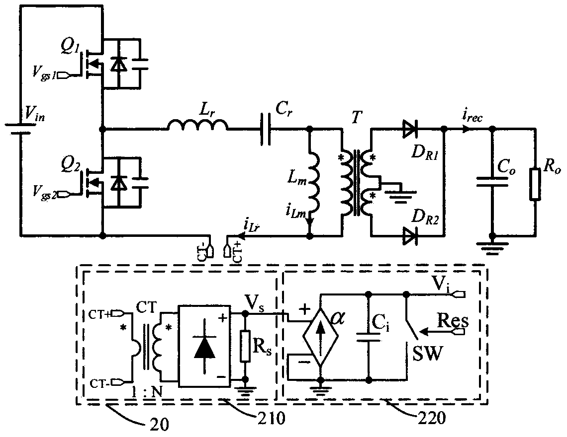
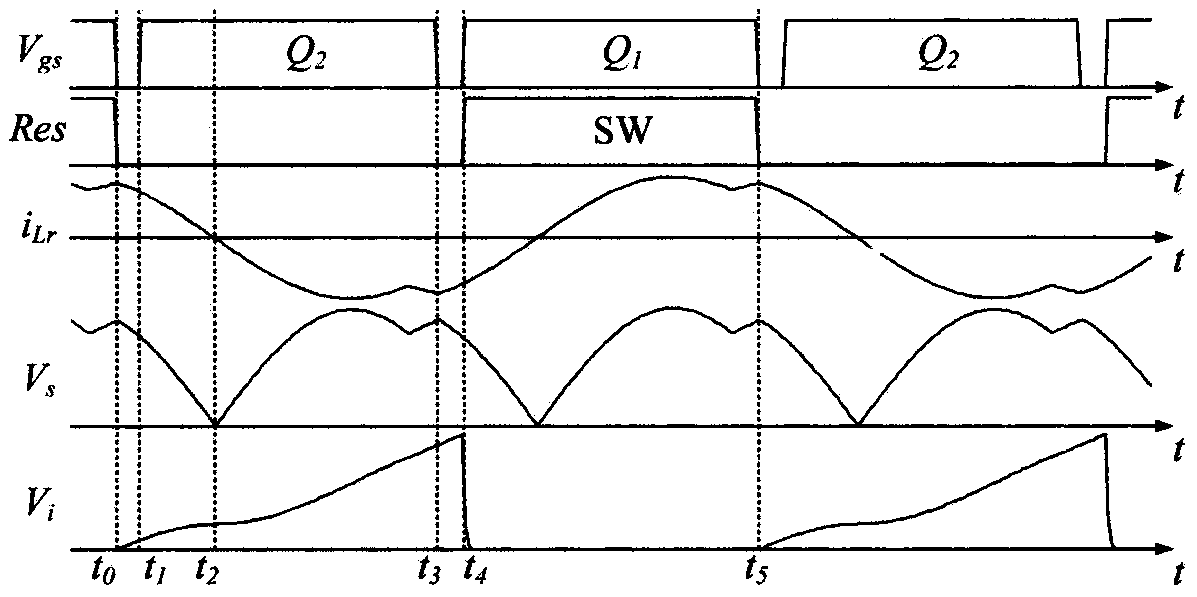
The invention discloses a current detection circuit of a resonant converter and a control method thereof. The current of a controlled branch is converted into an induction signal through a current sampling circuit, the induction signal is integrated through a resettable integrating circuit and then is output to an ADC of a digital controller for sampling, a current operation unit calculates the average information of the current of the controlled branch in an integration time period according to a sampling value, a PWM module and a drive amplifying unit output a drive signal after the averageinformation of the current is operated through a current regulator, a switch bridge arm of the converter is controlled, and the resettable integrating circuit is reset. The current of the resonance converter is rapidly detected and controlled, and dynamic performances of the converter can be improved.

Description

technical field [0001] The invention discloses a current detection circuit of a resonant converter and a control method thereof, belonging to the technical field of power electronic converters. Background technique [0002] The resonant converter refers to the use of the resonant components such as inductors and capacitors in the circuit to periodically cross zero current and voltage when resonance occurs, so that the switching device can realize zero-voltage (ZVS) or zero-current (ZCS) switching, that is, soft switching. The switching power supply tends to be high-frequency and miniaturized, so it has been widely used in high-frequency switching power supply occasions. The working principle of the commonly used DC-DC resonant converter is that the DC input voltage generates a square wave voltage after passing through the switch bridge arm, which is added to both ends of the resonant cavity to make the resonant circuit resonate, and the resonant voltage or resonant current o...

Claims


Application Information

Patent Timeline
IPC IPC(8): H02M3/335
CPCH02M3/33569H02M1/0009H02M1/0012Y02B70/10
Inventor 胡海兵杜士祥
Owner NANJING UNIV OF AERONAUTICS & ASTRONAUTICS
Learn More