Welding tool equipment

A welding tooling and equipment technology, applied in welding equipment, resistance welding equipment, metal processing equipment and other directions, can solve the problems of deformation of compressor shell mechanical parts, affecting compressor work efficiency, large heat affected zone, etc. Small heat-affected zone, good safety protection, good operation convenience

Pending Publication Date: 2019-08-13
刘悦吟
View PDF0 Cites 2 Cited by
  • Summary
  • Abstract
  • Description
  • Claims
  • Application Information

AI Technical Summary

Problems solved by technology

[0005] It can be seen from the structure of the above-mentioned conventional resistance welding welding equipment that when the conduction between the two welding electrodes is realized, the conduction current will pass through the large-area compressor shell, and may flow through the mechanical components inside the compressor; Under the thermal effect of the current, the heat-affected zone of the existing resistance welding equipment during welding is relatively large, which easily leads to deformation of the compressor shell and mechanical parts inside the compressor shell, affects the working efficiency of the compressor, and may cause cause compressor failure

Method used


Image

  • Welding tool equipment
  • Welding tool equipment
  • Welding tool equipment

Examples


Embodiment Construction

[0032] The following will clearly and completely describe the technical solutions in the embodiments of the present invention with reference to the accompanying drawings in the embodiments of the present invention. Obviously, the described embodiments are only some, not all, embodiments of the present invention. Based on the embodiments of the present invention, all other embodiments obtained by persons of ordinary skill in the art without creative efforts fall within the protection scope of the present invention.

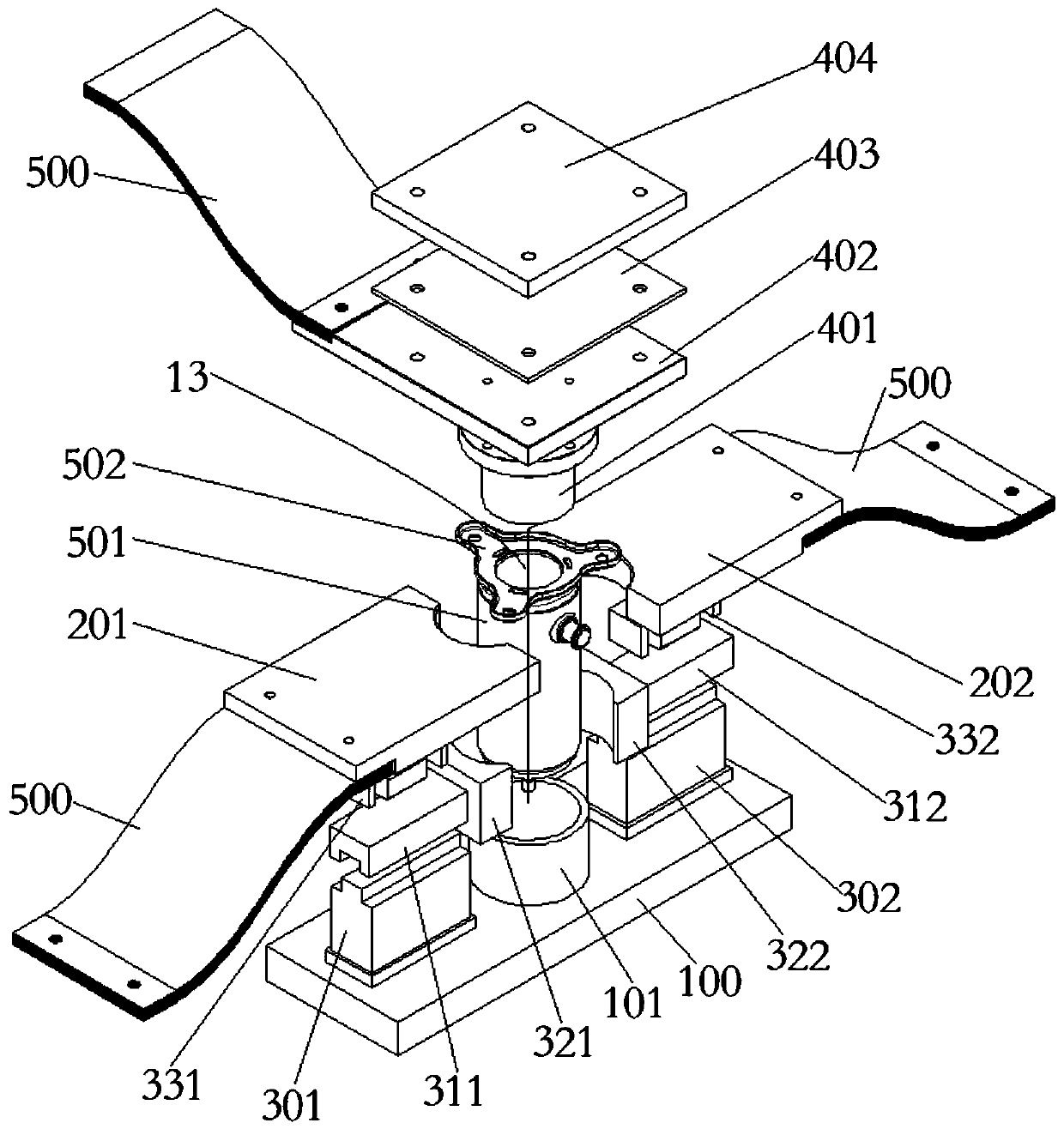
[0033] The invention provides a welding tooling equipment, which includes a base assembly, an upper electrode assembly and a lower electrode assembly;

[0034] The base assembly is fixed, the upper electrode assembly includes an upper electrode head, and the upper electrode head is arranged above the base assembly;

[0035] The upper electrode head moves toward or away from the base assembly, and when the upper electrode head moves toward the base assembly to the e...


PUM


Abstract

The invention provides welding tool equipment. The welding tool equipment comprises a base assembly, an upper electrode assembly and a lower electrode assembly. The base assembly is fixed. The upper electrode assembly comprises an upper electrode head. When the upper electrode head moves to the stroke end point in the direction of the base assembly, a welding space is formed between the bottom face of the upper electrode head and the base assembly. The lower electrode assembly comprises two or more lower electrodes. When the two or more lower electrodes move to the stroke end point towards thewelding space, the welding space is surrounded by the two or more lower electrodes, and the two or more lower electrodes are combined to form a lower electrode head. The welding pressure of the welding tool equipment is provided by the upper electrode head and the base assembly, the position of the lower electrode head can be freely arranged, and good practicality is achieved.

Description

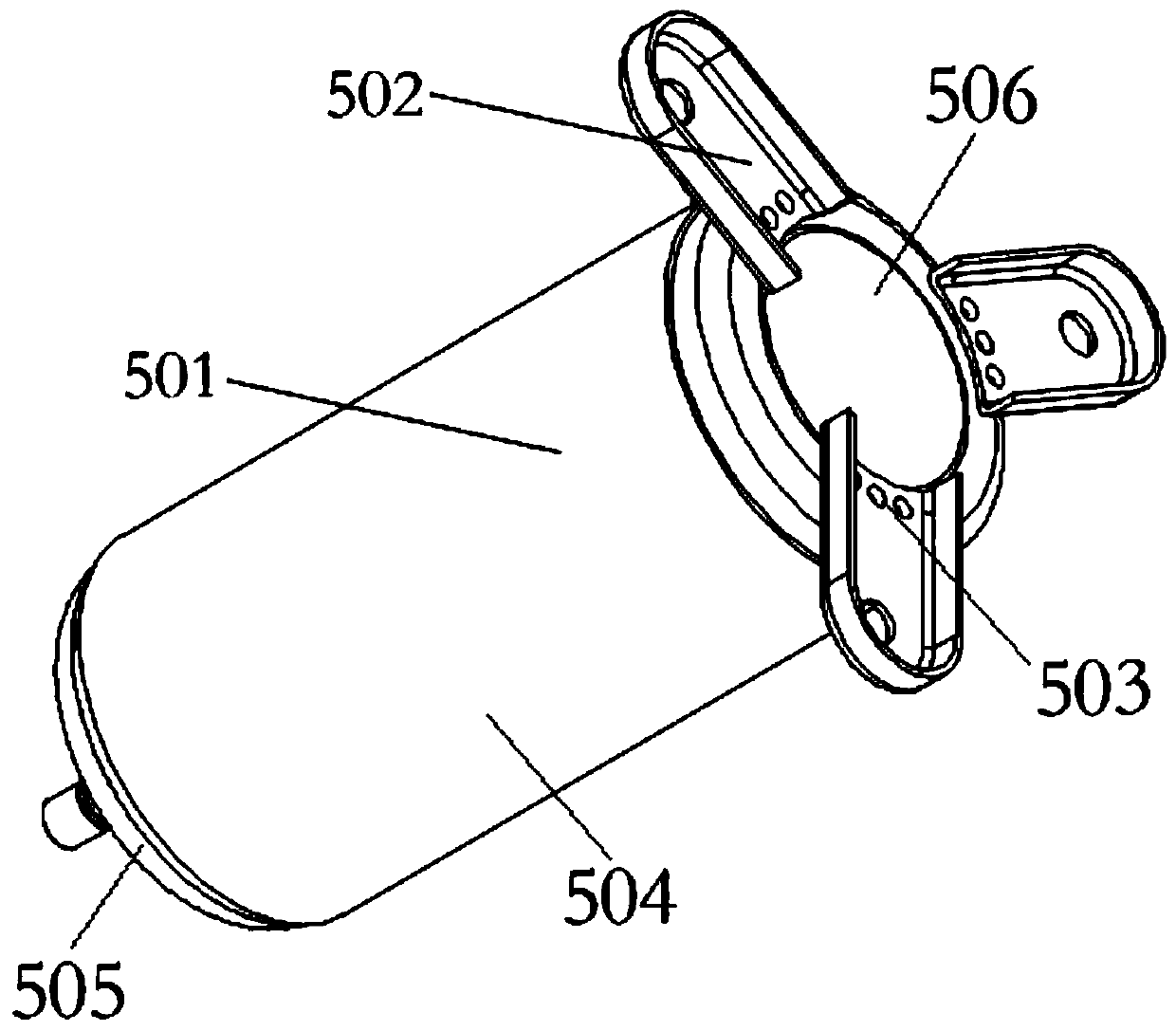
technical field [0001] The invention relates to the field of welding, in particular to a welding tool. Background technique [0002] Resistance welding refers to the method of using the resistance heat generated by the current passing through the weldment and the contact as the heat source to locally heat the piece and simultaneously pressurize it for welding. [0003] figure 1 A structural schematic diagram of a compressor is shown. In the industry, in order to realize the external installation of the compressor 501 , it is usually necessary to weld a compressor base 502 on the bottom of the compressor 501 . At present, gas shielded welding is usually used in the industry, but the use of gas shielded welding, on the one hand, has a high welding defect rate, on the other hand, due to high heat, the welding heat affected zone is large, resulting in deformation of the mechanical part of the compressor, affecting the efficiency of the compressor and even cause the compressor...

Claims


Application Information

Patent Timeline
IPC IPC(8): B23K11/00B23K11/02B23K11/30B23K11/36
CPCB23K11/02B23K11/36B23K11/30B23K11/002B23K11/3009
Inventor 刘悦吟
Owner 刘悦吟
Why Eureka
Try Eureka