
Laser shock processing device for blisk

A technology of laser shock strengthening and integral blisk, which is applied in the field of surface treatment of parts, can solve the problems of misalignment between the blade and the first blade, poor strengthening effect, low precision, etc., and achieve the reduction of the amount of motion trajectory programming of industrial robots , Shot peening effect improvement, the effect of improving the effect and efficiency

Inactive Publication Date: 2019-08-13
AVIC BEIJING INST OF AERONAUTICAL MATERIALS
View PDF8 Cites 4 Cited by
  • Summary
  • Abstract
  • Description
  • Claims
  • Application Information

AI Technical Summary

Problems solved by technology

However, before the program runs, the second blade needs to be calibrated. At present, the laser is often used to align the blade tip. This method judges the position by human eyes, and the accuracy is low, which will easily cause deviations in the position of the subsequent laser scanning area; in addition , during the installation or positioning process of the overall blisk, bolts are used to fix it, and the phenomenon that the tooling and the overall blisk are not in the same axis often occurs, causing the position of the subsequent blade to not coincide with the first blade, and it is also easy to cause the position of the subsequent laser scanning area to appear Deviation; the above problems can easily lead to problems such as low processing efficiency of the overall blisk, serious blade deformation, and poor strengthening effect

Method used


Image

  • Laser shock processing device for blisk

Examples


Embodiment Construction

[0018] The present invention will be described in further detail below in conjunction with the accompanying drawings.

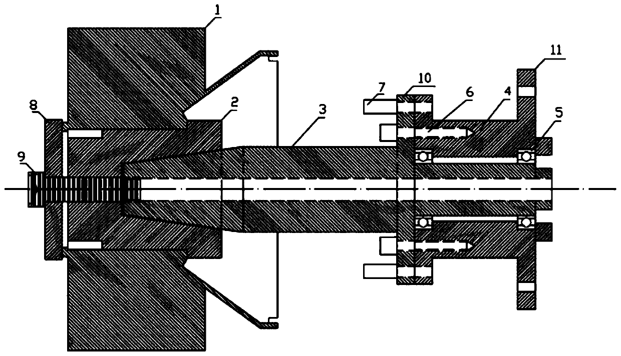
[0019] see figure 1 , The laser shock peening device of the whole blisk includes a shaft sleeve 2, a connecting rod 3, a base 4, a bearing 5, a screw 6, a positioning pin 7, a cover plate 8 and a central screw 9. The shaft sleeve 2 is cylindrical, with a central through hole at the left end of the shaft sleeve 2, and a central tapered hole at the right end of the shaft sleeve 2; the central hole of the blisk 1 is connected with the outer surface of the shaft sleeve 2 in a clearance fit The base 4 is cylindrical, the left end of the base 4 is a flange, and 6 screw holes and a plurality of positioning holes are evenly distributed, and the right end of the base 4 is a chassis 11, which is also a flange, and 6 bolt holes are evenly distributed; The left end of the connecting rod 3 is a tapered cylindrical shape, and the left end of the tapered rod 3 is connected...


PUM


Abstract

The invention discloses a laser shock processing device for a blisk. According to the device, the blisk 1 is fixed through a shaft sleeve 2, a cover plate 8 and a central screw 9 of the laser shock processing device; and through the location of a location pin 7 and the fixing of a screw 6, the central axis of the clamped blisk (1) is enabled to keep vertical to the end surface of a flange disc ofan industrial robot and keep coaxial with the flange disc of the industrial robot. In order to reduce the programming workload of the industrial robot, a second blade is rotated to the position of a first blade through the manner of rotating the flange disc 10 at the middle part, the industrial robot movement program of the first blade can be repeatedly called, and laser shock processing for the second blade and all the subsequent blades is realized, so that the workload is greatly reduced, and the program complexity is reduced.

Description

technical field [0001] The invention relates to a laser shock strengthening device for an integral blisk, which belongs to the technical field of parts surface treatment. Background technique [0002] The overall blisk of the aero-engine compressor is located at the front end of the engine. Not only is it subjected to multiple factors such as high stress and high speed, but the blades of the overall blisk face high-speed impacts such as sand, stone, hail, and birds. High risk of failure due to fatigue damage. Laser shock strengthening is an effective surface strengthening method to improve the overall blade disk of the compressor. The plasma shock wave induced by laser is used to act on the absorbing layer of the material surface, causing microscopic plastic deformation on the material surface, forming a high-amplitude residual compressive stress layer and Tissue hardening layer, thereby improving the overall fatigue performance of the overall blisk. The United States and ...

Claims


Application Information

Patent Timeline
Patent Type & Authority Applications(China)
IPC IPC(8): B23K26/356B23K26/70B23K37/04
CPCB23K37/0435B23K26/356B23K26/702
Inventor 罗学昆武艺王欣宋颖刚王强汤智慧
Owner AVIC BEIJING INST OF AERONAUTICAL MATERIALS
Learn More