Unified shader

a shader and unified technology, applied in the field of computer graphics, can solve the problems of reducing the size of the fifo used, and reducing the cost of synchronizing between a buffer register and a fifo, so as to achieve speed and efficiency. the effect of improving the efficiency of synchronizing and reducing the size of the fifo

Active Publication Date: 2010-09-14
ATI TECH INC
View PDF55 Cites 3 Cited by
  • Summary
  • Abstract
  • Description
  • Claims
  • Application Information

AI Technical Summary

Benefits of technology

[0020]In prior art systems, indirect texture and bump mapping would have required large FIFO memory structures. The unified shader in the present invention handles such mapping without the huge FIFOs and buffer register needed in a conventional texture shader. Instead, the internal clock scheduling mechanism and architecture ALU/SRAM pairs of the unified shader enable it to use only a single memory structure, which may be a FIFO. The FIFO in one embodiment may be placed in SRAM, which is speedier and more efficient than the conventional method of using a FIF

Problems solved by technology

Separate shaders make their use difficult and expensive.
For these reasons, color shaders are used for general applications of color while texture coordinate shaders have been limited to only performing high precision bump mapping displacement algorithms.
Moreover, the underlying drivers and computer hardware involved in shading must know whether it is dealing with a color or a texture coordinate, which is disadvantageous.
Another problem associated with multiple, limited shaders is i

Method used


Image

  • Unified shader
  • Unified shader
  • Unified shader

Examples


Embodiment Construction

[0033]The invention relates to a unified shader. In the following description, numerous specific details are set forth to provide a more thorough description of embodiments of the invention. It will be apparent, however, to one skilled in the art, that the invention may be practiced without these specific details. In other instances, well known features have not been described in detail so as not to obscure the invention.

[0034]Unified Shader

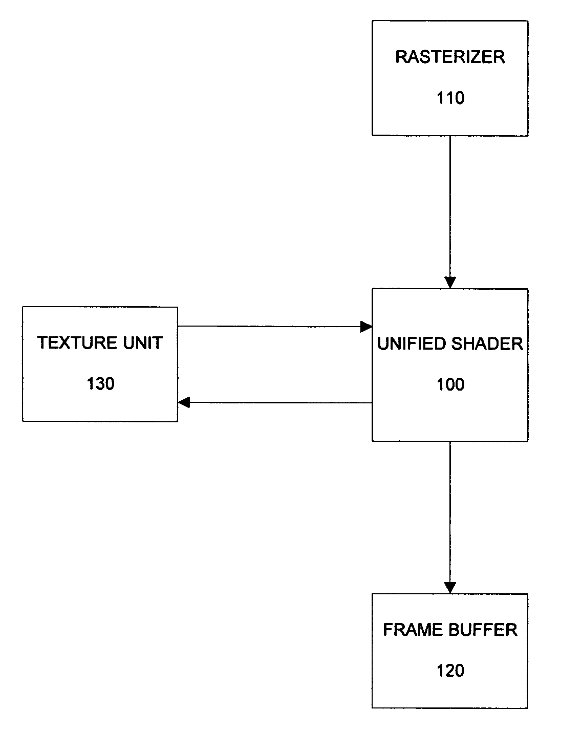
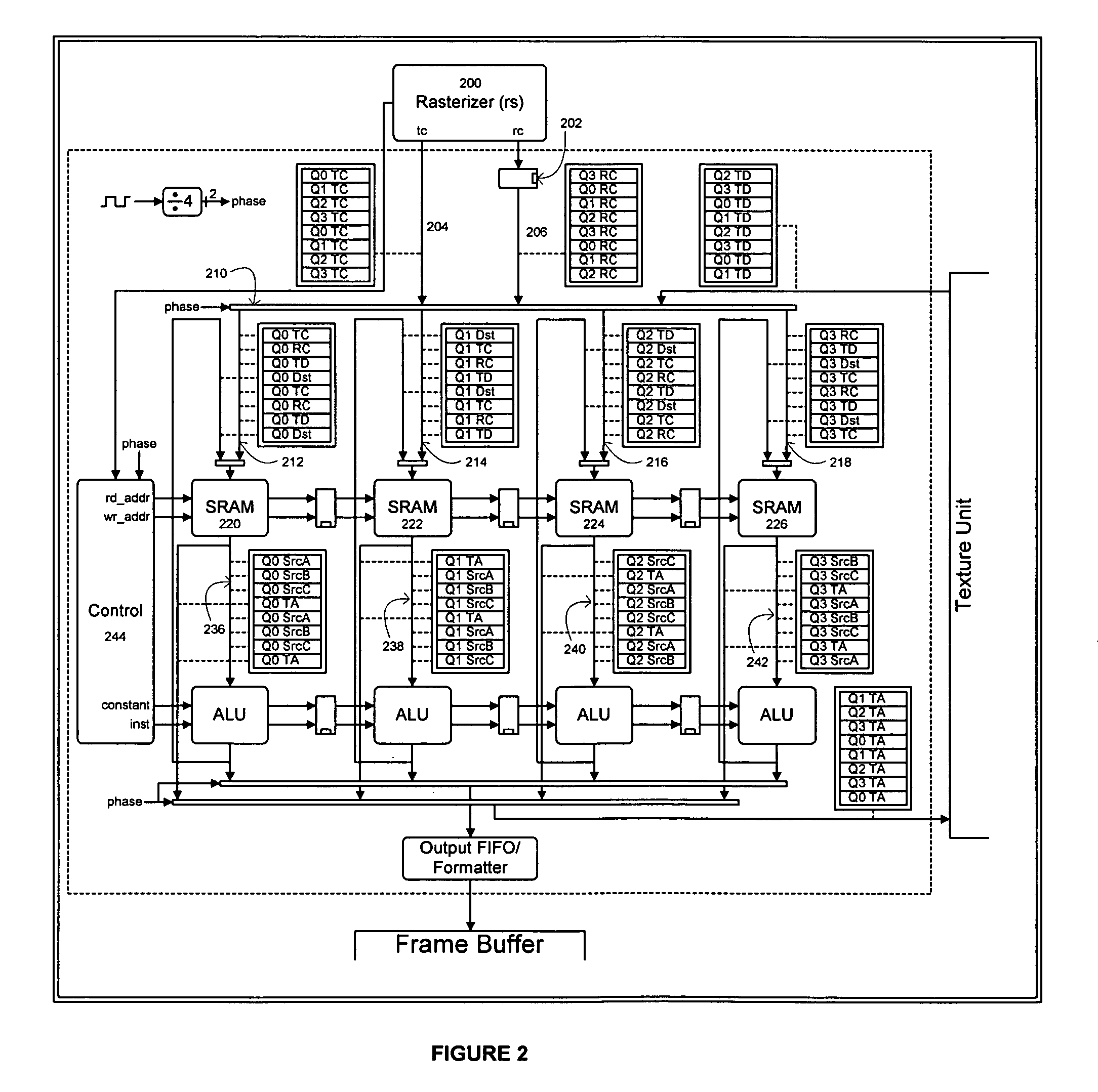
[0035]One embodiment of a unified shader is shown in the block diagram of FIG. 1. Unified shader 100 performs per-pixel shading calculations on rasterized values that are passed from a rasterizer unit 110. The results of the calculations are sent to frame buffer 120. As part of the calculation performed by unified shader 100, a texture unit 130 may receive texture lookup requests from the shader 100. The actual shading algorithm used may vary and may be defined by a set of instructions, such as microcode instructions.

[0036]Unified (Pixel) Shader ...


PUM


Abstract

The present invention is a unified shader unit used in texture processing in graphics processing device. Unlike the conventional method of using one shader for texture coordinate shading and another for color shading, the present shader performs both operations. The unified shader uses the same precision for both texture coordinate and color shading, thus simplifying the complexity of programming for two separate conventional shaders with different levels of precision. Furthermore, the present invention uses enhanced scheduling logic to perform indirect texture and bump mapping in a single first-in, first-out (FIFO) memory structure and avoids the problems associated with large FIFOs with buffer registers found in conventional shaders. In one embodiment, a plurality of ALU-memory pairs are synchronized to form a plurality of pipelines to execution shading instructions. In another embodiment, a plurality of unified shaders are synchronized and connected together to processing shading operations concurrently.

Description

RELATED APPLICATION[0001]This application is a continuation of U.S. application Ser. No. 10 / 716,946, filed Nov. 18, 2003, now abandoned which claims priority from U.S. provisional application No. 60 / 427,338, filed Nov. 18, 2002.BACKGROUND OF THE INVENTION[0002]1. Field of the Invention[0003]The present invention relates computer graphics. More specifically, one or more embodiments of the present invention relate to a unified shader.[0004]Portions of the disclosure of this patent document contain material that is subject to copyright protection. The copyright owner has no objection to the facsimile reproduction by anyone of the patent document or the patent disclosure as it appears in the Patent and Trademark Office file or records, but otherwise reserves all copyright rights whatsoever.[0005]2. Background Art[0006]Computer systems are often used to generate and display graphics on an output device such as a monitor. Display images are made up of thousands of tiny dots, where each do...

Claims


Application Information

Patent Timeline
IPC IPC(8): G06T15/50G09G5/02G06T11/40G09G5/00
CPCG06T15/005
Inventor LEATHER, MARK M.DEMERS, ERIC
Owner ATI TECH INC
Why Eureka
Try Eureka