Automatic ceramic chip feeding device for PTC (Positive Temperature Coefficient) heating element preparation

An automatic feeding and ceramic chip technology, applied in unloading devices, ceramic molding machines, manufacturing tools, etc., can solve the problems of time-consuming and labor-intensive quality, unguaranteed quality, and neat placement of four ceramic chips, etc., to achieve grasping Safe and reliable effect

Pending Publication Date: 2019-08-13
芜湖黑特新能源汽车科技有限公司
View PDF5 Cites 2 Cited by
  • Summary
  • Abstract
  • Description
  • Claims
  • Application Information

AI Technical Summary

Problems solved by technology

[0004] The traditional way of artificial ceramic sheet feeding is not only time-consuming and laborious, but also the quality cannot be guaranteed. After all, workers always slack off, and the traditional mechanical feeding method often cannot make the four ceramic sheets neatly arranged and in the correct position.

Method used


Image

  • Automatic ceramic chip feeding device for PTC (Positive Temperature Coefficient) heating element preparation
  • Automatic ceramic chip feeding device for PTC (Positive Temperature Coefficient) heating element preparation
  • Automatic ceramic chip feeding device for PTC (Positive Temperature Coefficient) heating element preparation

Examples


Embodiment 1

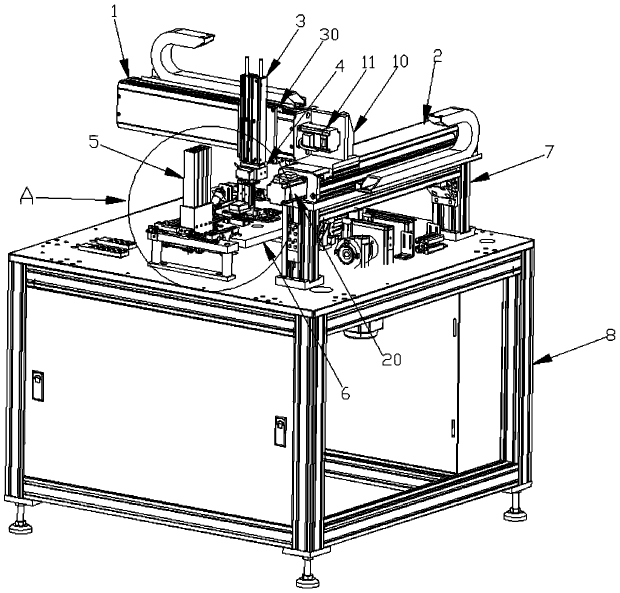
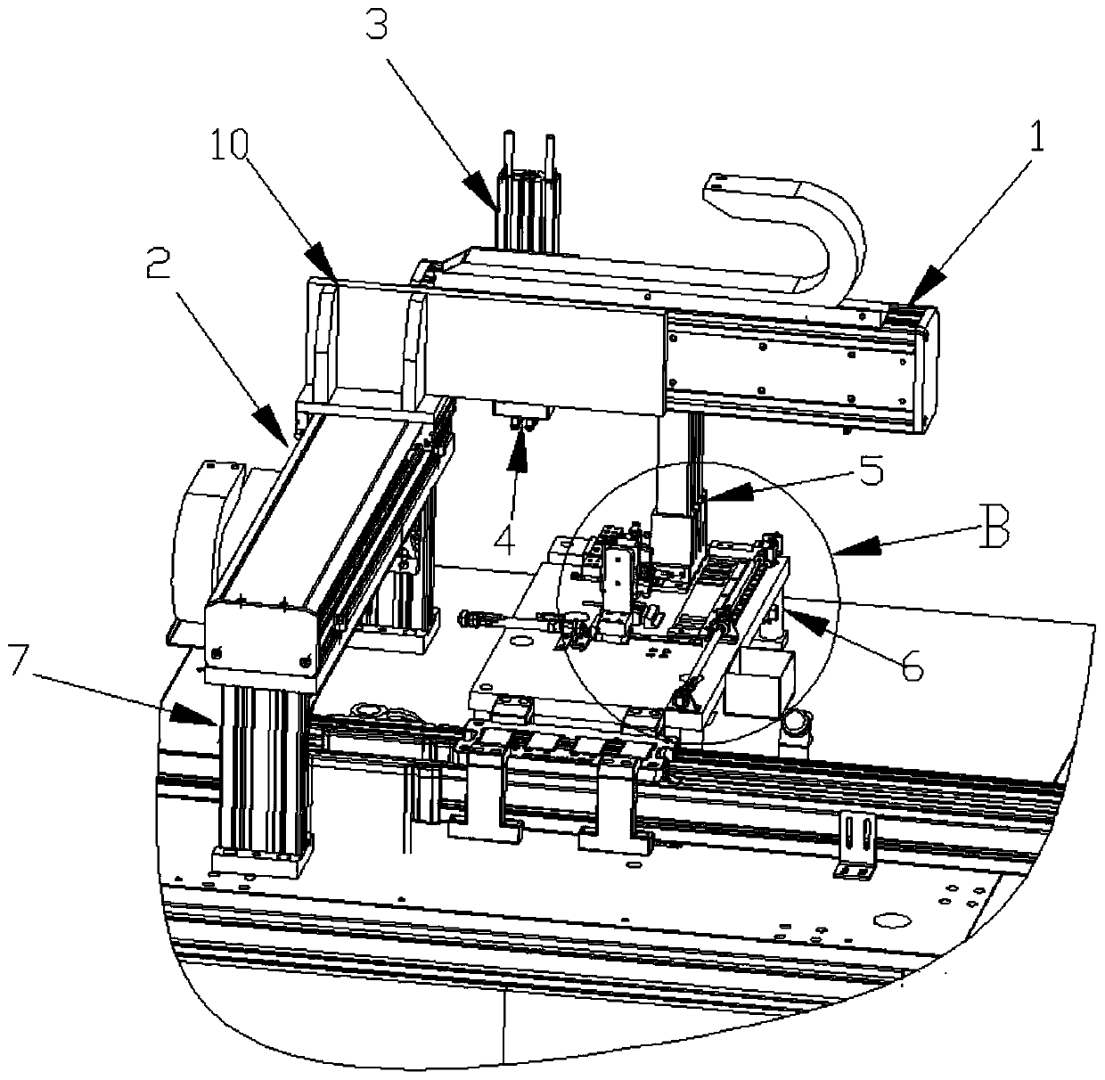
[0026] Such as Figure 1 to Figure 7 As shown, an automatic ceramic sheet feeding device for making PTC heating sheets, including X-axis track 1, Y-axis track 2, vertical cylinder 3, vacuum suction cup 4, ceramic sheet placement frame 5, processing platform 6 and abutment 8; Set X-axis track 1 and Y-axis track 2 to realize horizontal movement, set vertical cylinder 3 to realize vertical movement, and then realize three-dimensional movement.

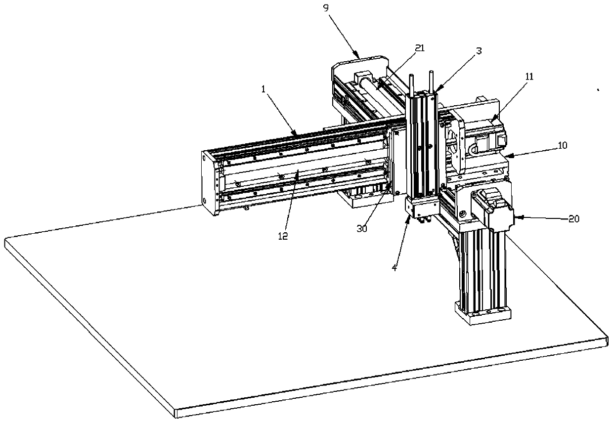
[0027] The Y-axis track 2 is fixedly connected to the abutment 8 through the feet 7 (a foot 7 is provided at the bottom of both ends of the Y-axis track 2 to play a load-bearing and stable role), and the X-axis track 1 is installed through the X-axis The seat 10 is slidingly connected with the Y-axis track 2, the vertical cylinder 3 is slidably connected with the X-axis track 1 through the cylinder mounting seat 30, and the vacuum chuck 4 is connected with the output shaft of the vertical cylinder 3; one end of the X-axis track 1 passes t...

Embodiment 2

[0031] Such as Figure 1 to Figure 7 As shown, an automatic ceramic chip feeding device for making PTC heating chips, including X-axis track 1, Y-axis track 2, vertical cylinder 3, vacuum chuck 4, ceramic chip placement frame 5, processing platform 6 and abutment 8;

[0032] The Y-axis track 2 is fixedly connected to the base 8 through the feet 7, the X-axis track 1 is slidably connected to the Y-axis track 2 through the X-axis mount 10, and the vertical cylinder 3 is connected to the X-axis through the cylinder mount 30. The track 1 is slidingly connected, and the vacuum chuck 4 is connected with the output shaft of the vertical cylinder 3;

[0033] The processing platform 6 is fixedly connected to the base platform 8, and the ceramic chip placement frame 5 is fixedly connected to the upper end of the processing platform 6. The processing platform 6 is also provided with a push-out cylinder 50, a ceramic chip groove 60 and a material receiving cylinder. 61, the ejection cylin...


PUM


Abstract

The invention discloses an automatic ceramic chip feeding device for PTC (Positive Temperature Coefficient) heating element preparation, and relates to the field of processing and preparation of PTC heating elements. The device comprises an X-axis rail, a Y-axis rail, a vertical cylinder, a vacuum chuck, a ceramic chip storing rack, a handling platform and a base platform. According to the device,the X-axis rail and the Y-axis rail are arranged to realize moving on the horizontal plane, and the vertical cylinder enables moving on a vertical plane, so that three-dimensional moving is achieved;and meanwhile, the vacuum chuck is used for picking the ceramic chip, so that the picking stability and safety are ensured; the ceramic chip storing rack is matched with a push-out cylinder to automatically push the ceramic chips, and four ceramic chips form a group; in addition, a ceramic chip groove is matched with a receiving cylinder to further take out the four pushed-out ceramic chips, andthe four ceramic chips are arranged regularly. Therefore, both time and power are saved by automatic feeding; in addition, the chuck for grabbing is safe and reliable; and moreover, the four ceramic chips can be regularly arranged.

Description

technical field [0001] The invention relates to the field of processing and manufacturing of PTC heating chips, in particular to an automatic ceramic sheet feeding device for making PTC heating chips. Background technique [0002] The PTC heating element contains the ceramic part. During the production and processing of the PTC heating element, the ceramic element needs to be transferred from the rack to the processing carrier for processing, which is commonly known as loading; [0003] The ceramic sheets in the PTC heating sheet are generally 4 small ceramic sheets put together. Although the ceramic sheet does not need to be calibrated like the electrode sheet before feeding, it is also necessary to ensure that the 4 ceramic sheets can be put together and placed neatly. Then they are sent to the correct position on the processing carrier together, and the error in the position should not be too large, so there is a big difference between ceramic sheet feeding and electrode ...

Claims


Application Information

Patent Timeline
Patent Type & Authority Applications(China)
IPC IPC(8): B65G47/91B65G49/08B65G47/82
CPCB65G47/912B65G49/08B65G47/82B65G2201/022
Inventor 吴强蔡晓航
Owner 芜湖黑特新能源汽车科技有限公司
Why Eureka
Try Eureka