Mine rock clamping and lifting device

A technology for lifting devices and rocks, applied in cranes, safety devices, transportation and packaging, etc., can solve the problems of heavy mine rocks, difficulty in adjusting lifting methods, and impact on the ground environment, etc., and achieve high practicability

Inactive Publication Date: 2021-06-25
邓腊平
View PDF0 Cites 0 Cited by
  • Summary
  • Abstract
  • Description
  • Claims
  • Application Information

AI Technical Summary

Problems solved by technology

[0003] The existing mine rock clamping and lifting devices have the following problems: the weight of mine rocks is generally relatively heavy, and during the lifting process of high-density rocks, it is necessary to accurately place the mechanical claws of the lifting device on the rock to be lifted , the existing devices often make the mechanical claws close to the lifting goods by moving the main body of the device, which is easily affected by the ground environment, and the lifting method is difficult to adjust, and the existing patents are not easy to solve such problems. Therefore, there is an urgent need for a mine Rock clamping lifting device to solve the above problems

Method used


Image

  • Mine rock clamping and lifting device
  • Mine rock clamping and lifting device
  • Mine rock clamping and lifting device

Examples


Embodiment 1

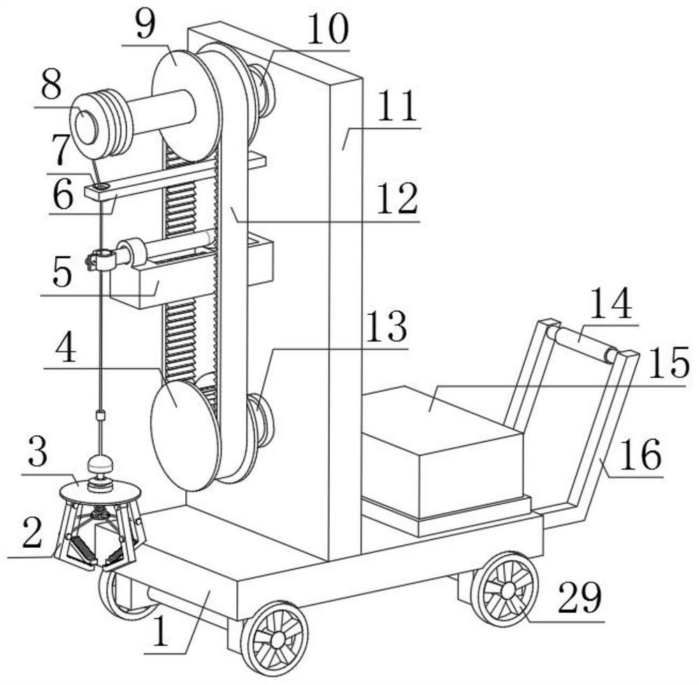
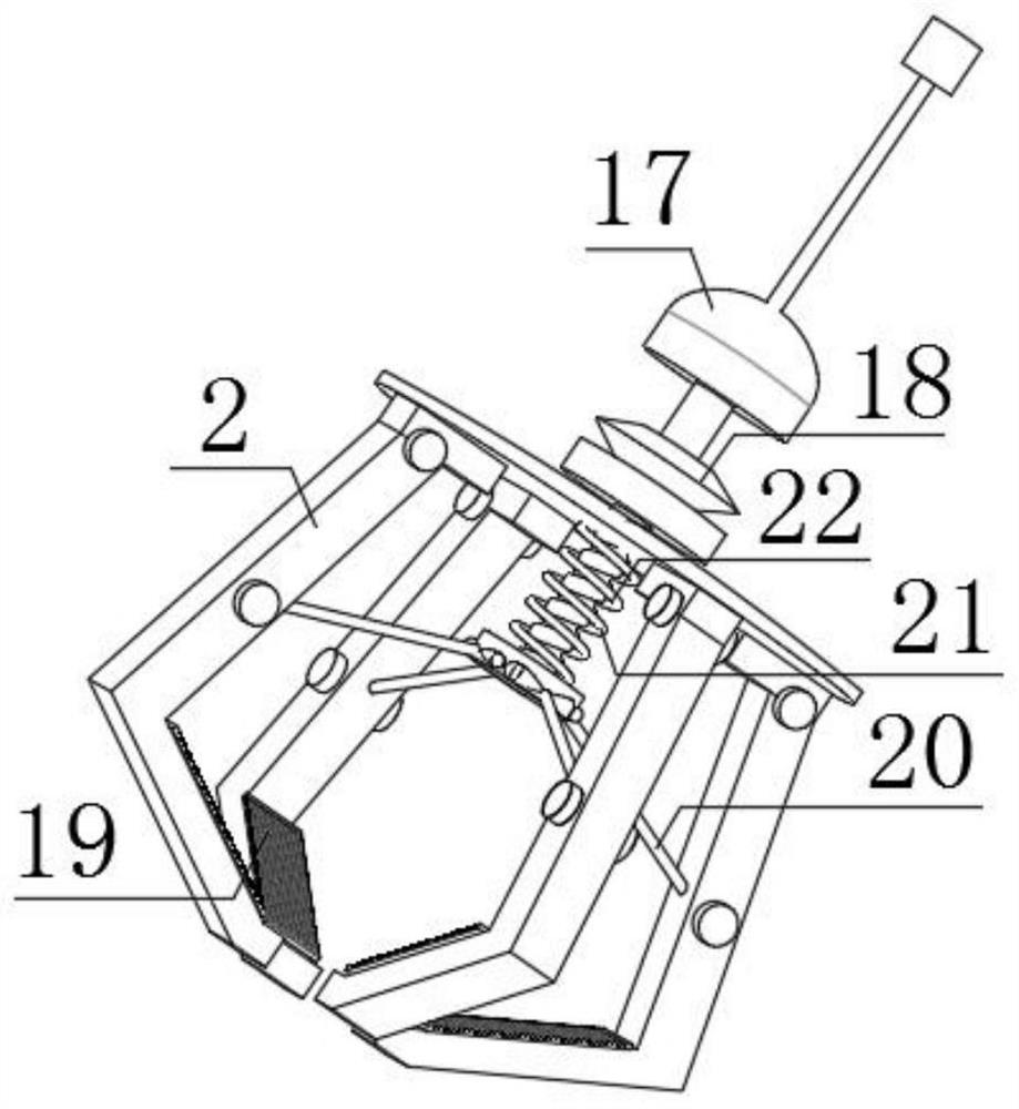
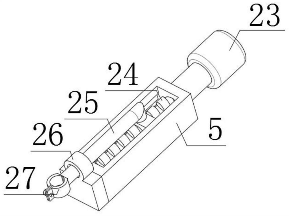
[0028] refer to Figure 1-4 , a mine rock clamping lifting device, comprising a base plate 1, a riser 11 is fixedly connected to the central position of the outer wall of the top of the base plate 1, and a driven rotating rod 10 is connected to the outer wall of one side of the riser 11 through a bearing. One end of the rod 10 is fixedly connected with the driven chainring 9, and the outer wall of one side of the driven toothed plate 9 is fixedly connected with the winch 8, and the outer wall of the winch 8 is wound with a traction rope, and the bottom end of the traction rope is fixedly connected with a connecting buckle 17. The bottom end of the connecting buckle 17 is provided with a grasping mechanism, and the outer wall of one side of the riser 11 is fixedly connected with the adjustment frame 5, and the inner wall of the adjustment frame 5 is connected with the second threaded rod 24 through a bearing, and the other side of the riser 11 One side outer wall is fixedly con...

Embodiment 2

[0039] refer to Figure 5 , a lifting device for clamping mine rocks. Compared with Embodiment 1, this embodiment further includes that a storage box 30 is fixedly connected to one side of the outer wall of the bottom plate 1 .

[0040] When in use, some tools needed in the mining process are placed in the storage box 30 arranged on one side of the bottom plate 1. During the lifting operation, when human assistance is needed, it is safer and more convenient to wear protective tools.


PUM


Abstract

The invention discloses a mine rock clamping and lifting device, and provides the following scheme aiming at the problems that an existing device is prone to being affected by the ground environment and the lifting manner is difficult to adjust due to the fact that a mechanical claw is made to get close to lifted goods by moving a device main body. The mine rock clamping and lifting device comprises a bottom plate; and a vertical plate is fixedly connected to the center of the outer wall of the top of the bottom plate, a driven rotating rod is connected to the outer wall of one side of the vertical plate through a bearing, a driven fluted disc is fixedly connected to one end of the driven rotating rod, a winch is fixedly connected to the outer wall of one side of the driven fluted disc, and a traction rope is wound around the outer wall of the winch. The bottom end of the traction rope is fixedly connected with a connecting buckle, and a grabbing mechanism is arranged at the bottom end of the connecting buckle. The drooping traction rope is buckled in a buckle plate, the grabbing mechanism connected to the lower portion of the traction rope is moved through pushing of a supporting rod, the adjusting effect of the grabbing mechanism is simply and flexibly achieved, and practicability is higher.

Description

technical field [0001] The invention relates to the technical field of mining machinery, in particular to a mine rock clamping lifting device. Background technique [0002] At present, mining machinery is the mechanical equipment used for direct mining of useful minerals and mining preparations. It mainly includes mining machinery for mining metal ore and non-metallic ore; coal mining machinery for mining coal; oil drilling machinery for oil mining. Mining machinery is mainly used for underground and open-pit mining, including drilling machinery for drilling blast holes; excavating machinery and loading and unloading machinery for digging and loading rock; Drilling machines are divided into rock drills and drilling rigs, and drilling rigs are divided into surface drilling rigs and downhole drilling rigs. A rock drill is a machine used to drill holes with a diameter of 20-100 mm and a depth of less than 20 meters in rocks above medium hardness. According to its power, it can...

Claims


Application Information

Patent Timeline
Patent Type & Authority Applications(China)
IPC IPC(8): B66C25/00B66C1/12B66C1/42B66C15/00B66C13/08B66C13/00
CPCB66C1/12B66C1/42B66C13/00B66C13/08B66C15/00B66C25/00
Inventor 邓腊平
Owner 邓腊平
Why Eureka
Try Eureka