Mask device
A mask and mask plate technology, which is applied in the direction of vacuum evaporation plating, coating, and electric solid devices, can solve the problems of mask plate wrinkles, affect evaporation yield, and mask plate is easy to sag, etc. Wrinkle and sagging amount, effect of deposition yield improvement
- Summary
- Abstract
- Description
- Claims
- Application Information
AI Technical Summary
Problems solved by technology
Method used
Image
Examples
Embodiment 1
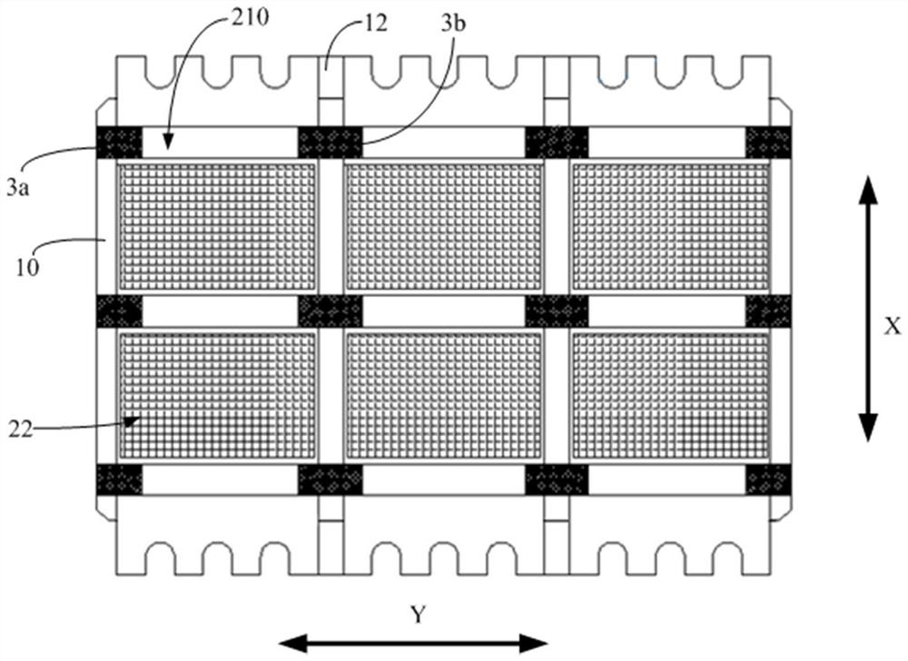
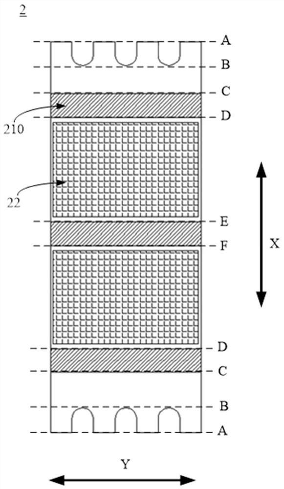
[0075] Such as figure 1As shown, the shrink sheet can be arranged on the side of the second surface 21 of the mask 2 facing away from the first surface 20 , that is to say, the shrink sheet can be connected to the second surface 21 of the mask 2 . However, since the aforementioned second surface 21 can be a glass contact surface, when the shrink sheet is connected to the second surface 21 of the mask plate 2, the thickness of the shrink sheet may cause the mask plate 2 and the evaporated screen to be separated. The distance between the bodies increases, which may cause shadows during evaporation. In order to solve this problem, the working area of the mask plate 2 in this embodiment not only includes the aforementioned evaporation area, but also includes A plurality of grooved areas arranged at intervals in the first direction X, the grooved areas include image 3 The area defined by the dotted line C and the dotted line D and the area defined by the dotted line E and the d...
Embodiment 2
[0085] Compared with Embodiment 1, the main differences of this embodiment are as follows: figure 1 As shown, one end of the second shrink sheet 3 b is installed in the installation groove 210 of one of the adjacent mask plates 2 , and the other end is installed in the installation groove 210 of the other of the adjacent mask plates 2 . That is to say, adjacent mask plates 2 can share the same shrink sheet. Other structures may be the same as those in Embodiment 1, and will not be repeated here.
Embodiment 3
[0087] Compared with Embodiment 1 and Embodiment 2, the main differences of this embodiment are: Figure 15 As shown, the shrink sheet is disposed on the side of the first surface 20 away from the second surface 21 ; that is, the shrink sheet can be connected to the first surface 20 of the mask plate 2 . However, when assembling the mask device, the frame structure is assembled first, and then the first surface 20 of the mask plate 2 is connected to the frame structure, such as Figure 13 shown; therefore, in order to facilitate the connection of the shrink sheet with the mask plate 2 and the frame body 10, as Figure 17 As shown, the vertical shielding sheet 12 in this embodiment can be provided with an assembly opening 120; Figure 13 and Figure 14 As shown, the assembly opening 120 can expose the parts on the frame body 10 and the mask plate 2 that need to be connected with the shrink sheet, so that the shrink sheet can be connected with the mask plate 2 and the frame bo...
PUM
 Abstract
Description
Claims
Application Information
 - R&D
- Intellectual Property
- Life Sciences
- Materials
- Tech Scout
- Unparalleled Data Quality
- Higher Quality Content
- 60% Fewer Hallucinations
Browse by: Latest US Patents, China's latest patents, Technical Efficacy Thesaurus, Application Domain, Technology Topic, Popular Technical Reports.
© 2025 PatSnap. All rights reserved.Legal|Privacy policy|Modern Slavery Act Transparency Statement|Sitemap|About US| Contact US: help@patsnap.com


