Cooling water system and control method thereof

A cooling water system and control method technology, applied in air conditioning systems, water shower coolers, heating methods, etc., can solve problems such as increased equipment investment costs and construction costs, increased cooling water system resistance, and increased long-term energy consumption. Achieve the effect of saving project cost, easy transformation and modification, and stable operation

Pending Publication Date: 2019-08-13
广东新菱空调科技有限公司
View PDF0 Cites 14 Cited by
  • Summary
  • Abstract
  • Description
  • Claims
  • Application Information

AI Technical Summary

Problems solved by technology

However, due to the addition of a pipe, there are the following disadvantages: since the central air-conditioning unit and circulating water pump are mostly installed in the basement, and the cooling tower is mostly installed outdoors where the air circulates, the distance between the pipes is relatively long, and the addition of pipes will inevitably lead to equipment failure. The investment cost and construction cost have increased significantly, and the addition of pipelines will increase the valve equipment at the same time, the resistance of the cooling water system will also increase accordingly, the head of the circulating water pump will also need to be increased, and the energy consumption for long-term operation will also increase accordingly
But this kind of debugging is based on the debugging of all water pumps at full power and full load. Most of the time when the system is actually running is low flow, and the flow of circulating water changes at any time due to the compliance of the central air conditioning unit. Initial debugging does not have much role and effect in the daily application of the system

Method used


Image

  • Cooling water system and control method thereof

Examples


Embodiment

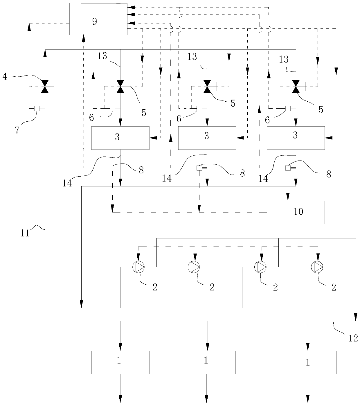
[0022] refer to figure 1 , is a cooling water system, including several refrigeration units 1, a cooling water circuit, several cooling water pumps 2 arranged in parallel on the cooling water circuit, cooling water branches arranged in parallel on the cooling water circuit, parallel arranged on the cooling water circuit Several cooling towers 3 on the water branch road are provided with fans in the cooling tower 3, wherein the cooling water circuit includes the water inlet main pipe 11 and the water return main pipe 12, and the cooling water branch road includes the water inlet branch pipe 13 and the water return branch pipe 14, and is also provided with There are a cooling system balance controller 9 and a cooling water pump frequency conversion controller 10, a main pipe flow balance valve 4 for controlling the total amount of water inflow is provided on the water inlet main pipe 11, and a main pipe flow balance valve 4 for controlling the total amount of water inlet is provi...


PUM


Abstract

The invention discloses a cooling water system and a control method thereof. The cooling water system comprises a refrigerator unit, a main water inlet pipe, a cooling water pump, secondary water inlet pipes, cooling towers, a cooling system balancing controller, a main pipe flow rate balancing valve which is arranged on the main water inlet pipe, and a secondary pipe flow rate balancing valve which is arranged on the secondary water inlet pipe. The control method comprises the following steps: detecting main water inlet flow rate parameters in the main water inlet pipe; determining the quantity of started cooling towers based on the minimum water inlet flow rate of each cooling tower; detecting the water inlet flow rate in each secondary water inlet pipe; adjusting the opening degree of the secondary pipe flow rate balancing valve based on the maximum water inlet flow rate of each cooling tower; controlling the actual flow rate of the secondary water inlet pipes to be not greater thanthe maximum water inlet flow rate of the cooling towers; detecting the total water inlet flow rate in the main water inlet pipes and the quantity of the cooling tower in a starting state; determiningthe average water inlet flow rate of each cooling tower in the starting state; and outputting the average water inlet flow rate as the actual set flow rate to each secondary pipe flow rate balancingvalve in order to adjust the opening degree of each secondary pipe flow rate balancing valve. The system realizes hydraulic balance, and is energy saving and stable in running.

Description

technical field [0001] The invention relates to a technology for controlling the balance of cooling water, in particular to a technology for controlling the water balance of a variable flow cooling water system. Background technique [0002] A common central air-conditioning system includes several refrigeration units, several circulating water pumps, and several cooling towers. The refrigeration units provide chilled water for fan coil heat exchange, and the circulating water pumps drive cooling water to circulate between the refrigeration units and cooling towers. The water exchanges heat with the air in the cooling tower, and the cooled cooling water is sent to the refrigeration unit through the circulating water pump for cooling. The main purpose of setting up the cooling water system in the central air-conditioning system is to exchange the heat of the condenser with the atmosphere to obtain low-temperature water for the operation of the central air-conditioning unit. ...

Claims


Application Information

Patent Timeline
Patent Type & Authority Applications(China)
IPC IPC(8): F24F5/00F24F11/89F28C1/00F28F25/00
CPCF24F5/0003F24F11/89F28C1/00F28C2001/006F28F25/00F28F2025/005Y02B30/70
Inventor 谭小卫
Owner 广东新菱空调科技有限公司
Why Eureka
Try Eureka