
Divergence angle adjustable beam expander

A technology of beam expander and divergence angle, applied in the direction of optical components, optics, instruments, etc., can solve the problems of small adjustment range, low positioning accuracy, and poor adjustment accuracy, and achieve high safety and reliability, simple installation and debugging, and adjustment accuracy high effect

Pending Publication Date: 2019-08-13
BEIJING ORIENTAL SHARP LASER TECH
View PDF0 Cites 1 Cited by
  • Summary
  • Abstract
  • Description
  • Claims
  • Application Information

AI Technical Summary

Problems solved by technology

[0003] At present, the divergence angle adjustment of the laser beam expander is mostly adjusted by adding gaskets of different thicknesses under the beam expander lens. Each adjustment needs to disassemble the lens. The adjustment efficiency is low, the adjustment range is small, the adjustment accuracy is poor, and it is difficult to control the expansion. The coaxiality between the beam lenses, and it is easy to cause material waste
[0004] Or design two laser beam expanders in a laser emission path for adjustment, and one of the beam expanders is designed as a structure that can change its position. When a large laser divergence angle is required, move this laser beam expander out of the optical path. When a small laser divergence angle is required, the laser beam expander is moved into the laser optical path. The positioning accuracy of this transposition method is limited by the size accuracy of the circular stop and positioning, and the positioning accuracy is low.

Method used


Image

  • Divergence angle adjustable beam expander
  • Divergence angle adjustable beam expander
  • Divergence angle adjustable beam expander

Examples


Embodiment 1

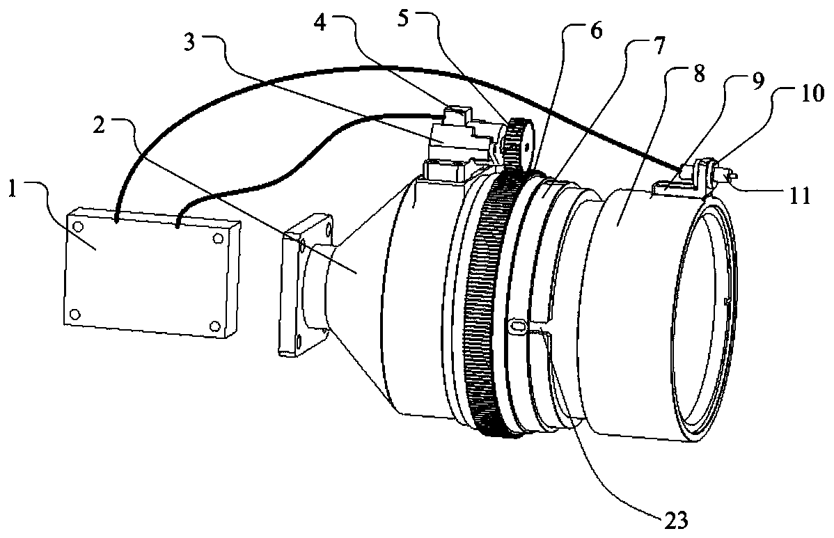
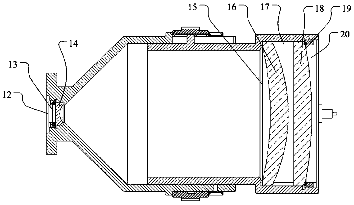
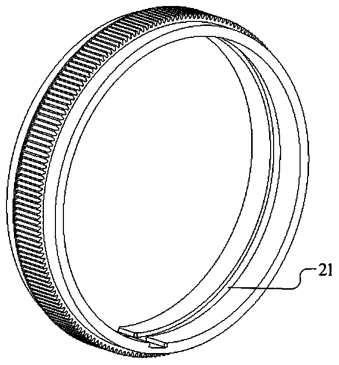
[0026] see Figure 1 to Figure 4 , a beam expander with adjustable divergence angle, including a drive control circuit 1, a first beam expander barrel 2, a second beam expander barrel 8, a stepping motor 4, a limit sensor 11, the first beam expander The head of the lens barrel is sleeved on the afterbody of the second beam expander lens barrel, the driving gear 5 is installed on the output shaft of the stepping motor, and the driven gear 6 and the gear limiter are sleeved on the first beam expander lens barrel. Position lock ring 7, the gear limit lock ring is fixed on the first beam expander lens barrel, the driving gear meshes with the driven gear, and the inner side of the driven gear is provided with annular guides with different pitches Slot 21, the tail of the second beam expander barrel is provided with a plurality of guide columns 22, the head of the first beam expander lens barrel is provided with a plurality of open grooves 23, and the plurality of guide columns pass...


PUM


Abstract

The invention discloses a divergence angle adjustable beam expander. The divergence angle adjustable beam expander comprises a drive control circuit, two beam expanding lens barrels, a stepping motorand a limit sensor, the head part of a first beam expanding lens barrel sleeves the tail part of a second beam expanding lens barrel; a driving gear is arranged on an output shaft of the stepping motor; a driven gear sleeves the first beam expanding lens barrel; the driving gear is engaged with the driven gear; annular guide grooves with different screw pitches are formed in the inner side of thedriven gear; a plurality of guide posts are arranged at the tail part of the second beam expanding lens barrel; a plurality of open slots are formed at the head part of the first beam expanding lens barrel; the guide posts respectively penetrate through the open slots and are matched with the annular guide grooves; a beam expanding ocular lens is arranged in the first beam expanding lens barrel; aplurality of beam expanding objective lenses are arranged in the second beam expanding lens barrel; and the limit sensor is fixed on the second beam expanding lens barrel, and drive control circuit is connected with the stepping motor and the limit sensor. The divergence angle adjustable beam expander can achieve the large-range regulation of the laser beam divergence angle, and is small in size,stable in structure and high in regulation precision.

Description

technical field [0001] The invention relates to the technical field of laser beam expansion and collimation, in particular to a beam expander with adjustable divergence angle. Background technique [0002] Laser has the advantage of strong collimation and has been widely used in many industries of national economic construction. However, the laser is a parallel light with a divergence angle, which makes the laser spot larger when the laser is emitted to a long distance, and the energy per unit area becomes weaker. In order to change the laser spot size of the emitted laser beam at a certain position, it is necessary to change the laser divergence angle, so a laser beam expander is designed in the laser emitting light path. Generally, the laser divergence angle is changed by defocusing. The specific method is to adjust the distance between the beam expander objective lens and the beam expander eyepiece to achieve the purpose of adjusting the laser divergence angle. [0003]...

Claims


Application Information

Patent Timeline
IPC IPC(8): G02B27/09
CPCG02B27/0933
Inventor 谢兰强韩薇薇赵虎云子艳乔迁韩天亮
Owner BEIJING ORIENTAL SHARP LASER TECH
Learn More