
Sweeping car for ion scraps and oil stains

A technology for cleaning vehicles and iron filings, which is applied in the direction of cleaning carpets, floors, and cleaning equipment. It can solve the problems of high labor intensity, personnel punctures, and punctures, and achieve the effect of increasing the difficulty of cleaning and facilitating cleaning.

Pending Publication Date: 2019-08-16
CHANGSHA AERONAUTICAL VACATIONAL AND TECHNICAL COLLEGE
View PDF0 Cites 0 Cited by
  • Summary
  • Abstract
  • Description
  • Claims
  • Application Information

AI Technical Summary

Problems solved by technology

[0002] During the mechanical processing of the factory, a large amount of iron filings will be produced, and cutting coolant is often used in the processing process. The iron filings will also be accompanied by cutting coolant, and there is also oil pollution on the ground of the factory. If these iron filings, If the oil stains are not removed in time, it will not only affect the site environment, but also cause people to be punctured and tires to be punctured. At present, the existing methods of cleaning iron filings in my country are generally manual cleaning, and watering and mopping is required after cleaning; The cleaning method has low work efficiency, high labor intensity for workers, and it is easy to step on iron filings during the cleaning process, causing the soles to puncture and stab people; therefore, there is an urgent need for a cleaning vehicle for iron filings and oil stains.

Method used


Image

  • Sweeping car for ion scraps and oil stains
  • Sweeping car for ion scraps and oil stains
  • Sweeping car for ion scraps and oil stains

Examples


Embodiment Construction

[0024] The embodiments of the present invention will be described in detail below with reference to the accompanying drawings, but the present invention can be implemented in various ways defined and covered by the claims.

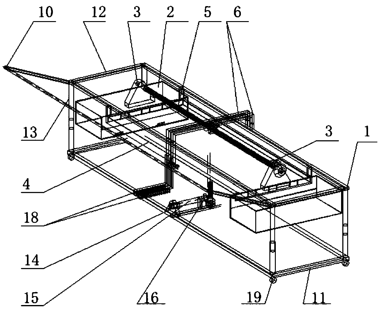
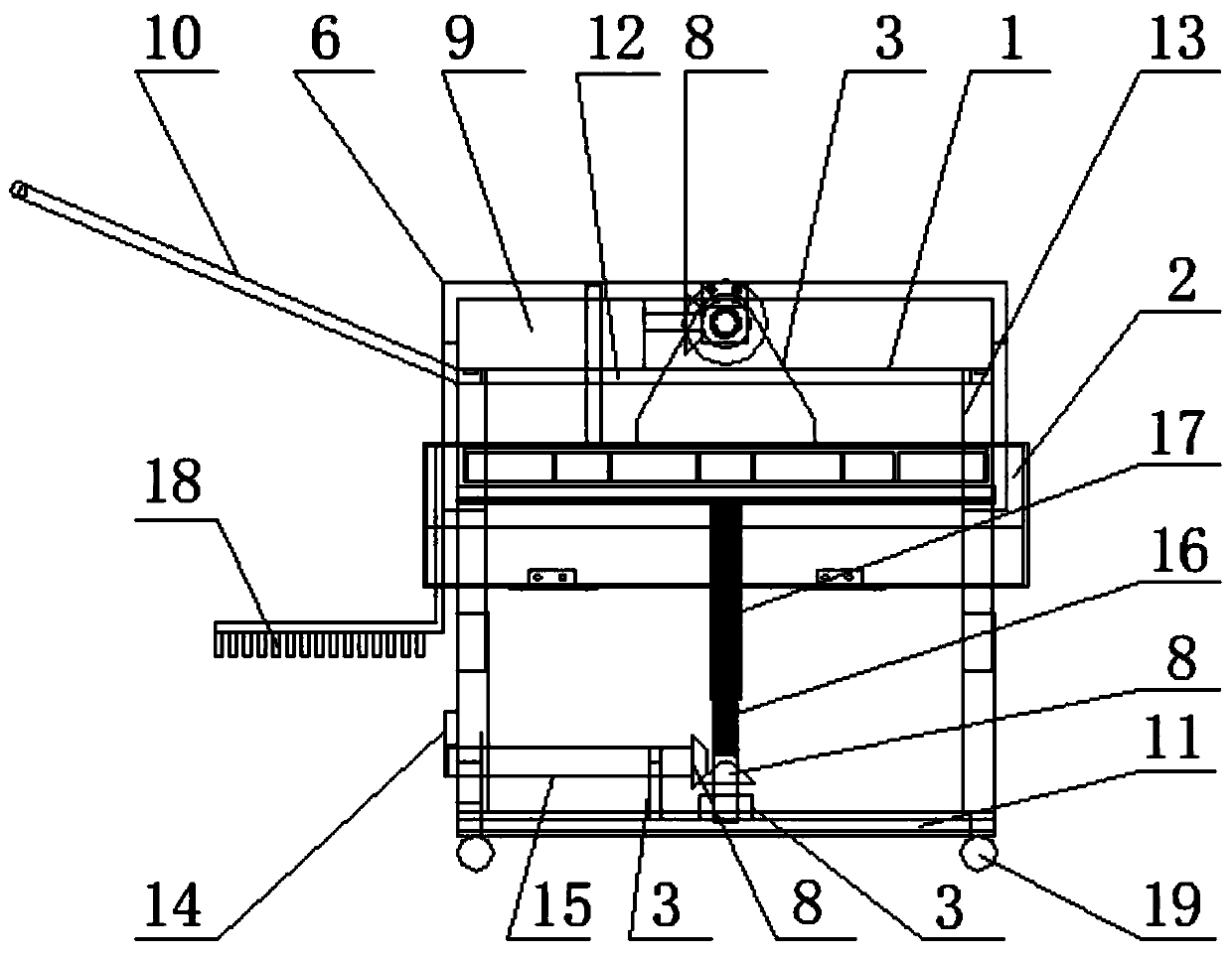
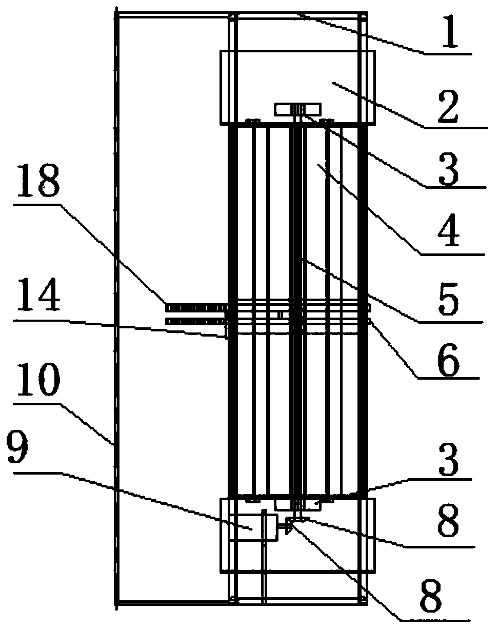
[0025] see Figure 1 to Figure 5 , an iron filings oil stain cleaning vehicle, comprising a lifting support frame 1, an iron filings collection box 2, a ferromagnetic plate 4, a lifting mechanism, an iron filings separation mechanism, an oil brush 18 and a universal wheel 19; the lifting support frame 1 includes the first A support frame 11, the second support frame 12 and the elevating rod 13, the elevating rod 13 is used for the supporting connection of the first supporting frame 11 and the second supporting frame 12, and one end of the elevating rod is connected with the first supporting frame, and the other end of the elevating rod One end is connected with the second support frame; in the present embodiment, the quantity of elevating rods is four piec...


PUM


Abstract

The invention provides a sweeping car for iron scraps and oil stains. The sweeping car comprises a lifting support frame, iron scrap collecting boxes, a ferromagnetic attracting plate, a lifting mechanism, an iron scrap separating mechanism, oil brushes and universal wheels; the lifting mechanism comprises a handle, a transmission shaft, an internal threaded rod and an external threaded rod. The iron scrap separating mechanism comprises separation brackets, bidirectional ball screws and a driving motor. According to the sweeping car, the distance between the ferromagnetic attracting plate andthe ground can be adjusted by rotating the handle to drive the internal threaded rod to be in fit connection with the external threaded rod, and therefore the magnetic force of the ferromagnetic attracting plate is controlled; lifting rods in the lifting support frame can adjust the distance between separation plates in the separation brackets and the ferromagnetic attracting plate so that the separation plates are always attached to a magnetic attracting surface of the ferromagnetic attracting plate; through the clockwise and counterclockwise rotation of the driving motor, the two separationbrackets on the bidirectional ball screws move back and forth, the separation plates push iron scraps on the ferromagnetic attracting plate into the iron scrap collecting boxes at the two ends respectively, and the oil brushes connected with the separation brackets can also move back and forth to wipe off oil stains on the ground.

Description

technical field [0001] The invention relates to the field of iron filings oil stain cleaning, in particular to an iron filings oil stain cleaning vehicle. Background technique [0002] During the mechanical processing of the factory, a large amount of iron filings will be produced, and cutting coolant is often used in the processing process. The iron filings will also be accompanied by cutting coolant, and there is also oil pollution on the ground of the factory. If these iron filings, If the oil stains are not removed in time, it will not only affect the site environment, but also cause people to be punctured and tires to be punctured. At present, the existing methods of cleaning iron filings in my country are generally manual cleaning, and watering and mopping is required after cleaning; The working efficiency of the cleaning method is low, the labor intensity of the workers is high, and the iron filings are easy to be stepped on during the cleaning process, causing the sole...

Claims


Application Information

Patent Timeline
IPC IPC(8): A47L11/24A47L11/40
CPCA47L11/24A47L11/40A47L11/4036A47L11/4041A47L11/4069
Inventor 沈宇峰何幸保黄登红
Owner CHANGSHA AERONAUTICAL VACATIONAL AND TECHNICAL COLLEGE
Learn More