Sand screening device for construction

A screening device, sand technology, applied in the direction of filter screen, solid separation, grid, etc., can solve problems such as clumping together, poor screening efficiency, uneven sand distribution, etc., to improve sand screening efficiency and speed up screening speed effect

Inactive Publication Date: 2019-08-16
南京市月华路小学
View PDF14 Cites 10 Cited by
  • Summary
  • Abstract
  • Description
  • Claims
  • Application Information

AI Technical Summary

Problems solved by technology

[0003] The retrieval authorization announcement number is CN104438066B discloses a kind of building sand screening machine, comprises frame, and the top side of described frame is arranged with pipe cover, and disc spring is arranged in described pipe cover, and the other side of described frame There is a bracket on the side, and the No. 1 motor is arranged on the bracket. The motor shaft of the No. 1 motor is provided with an eccentric wheel. The top of the disc spring and the eccentric wheel is provided with a No. 1 screen. A crossbeam, the middle position of the crossbeam is vertically provided with a through hole, the through hole is provided with a bearing, the bearing is provided with a rotating shaft, the top of the rotating shaft is provided with a No. 2 screen, and the bottom of the rotating shaft It is connected to the output end of the No. 2 motor. Through the setting of the No. 1 sieve and the No. 2 sieve, the thickness of the sieved sand is more uniform. Although this patent can sieve the sand evenly, there are still defects. Put it directly into the device for screening. If the sand is wet and agglomerated, the screening will be blocked, resulting in poor screening efficiency.
[0004] The retrieval authorization announcement number is CN104984895B, which discloses a sand screening device capable of secondary screening. The middle part of the longitudinal beam of the L-shaped frame body is movably connected to the sand screening unit, and the sand screening unit is composed of a sliding sleeve set on the longitudinal beam of the L-shaped frame body and can rotate along its axial direction, an annular bracket arranged on the sliding sleeve, a plug-in The sand screening cylinder installed in the ring bracket, the sand inlet provided on the upper surface of the sand screening cylinder, a pair of arc-shaped sand outlets provided on the lower surface of the sand screening cylinder, the sand brushing mechanism and the buckle arranged in the sand screening cylinder The primary screen connected to the opening of the upper end of the sand screening cylinder and the secondary screen arranged at the annular sand outlet on the lower surface of the sand screening cylinder are jointly constituted. The other end of the upper surface of the base is provided with a conveyor belt, and the upper end of the conveyor belt is located Just above the funnel, there is a control panel on the longitudinal beam of the L-shaped frame body. Although this patent can sieve sand twice to improve the sand sieving efficiency, the sand is directly put into the device for screening. If the sand is wet and agglomerated, the screening Blocked, resulting in poor screening efficiency
[0005] The existing sand sieving device is directly put in the sand, because the sand is often wet and clumped together, if it is directly put in for screening, the sand may be piled up and distributed unevenly, so that the vibrating sieve plate is not screened properly. Thoroughly, the screening efficiency is not high, in order to solve the above problems, we propose a sand screening device for construction

Method used


Image

  • Sand screening device for construction
  • Sand screening device for construction
  • Sand screening device for construction

Examples


Embodiment 1

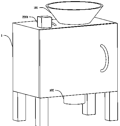
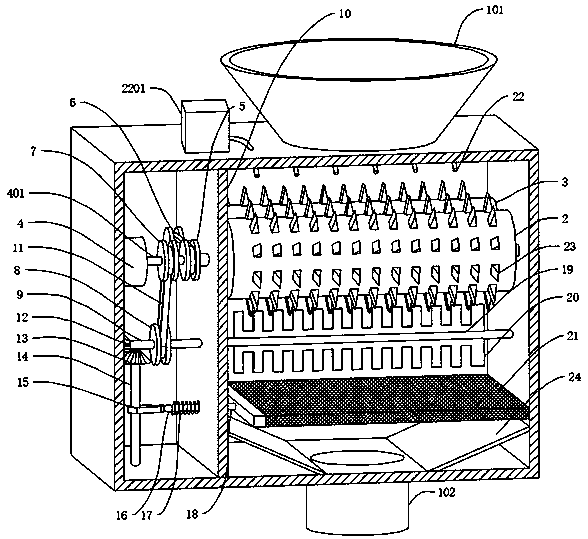
[0034] refer to Figure 1-3 , a sand screening device for construction, comprising a screening box 1 and a vibrating screen plate 21, the top of the screening box 1 is connected with a feed port 101, the bottom of the screening box 1 is connected with a discharge port 102, and the inner side wall of the screening box 1 is connected with a partition 10. The partition 10 divides the screening box 1 into a drive chamber and a screening chamber. The inner wall of the screening chamber is connected to the first rotating shaft 201 and the second rotating shaft 301 in rotation, and the outer walls of the first rotating shaft 201 and the second rotating shaft 301 are respectively connected to the first rotating shaft. The pressing roller 2 and the second pressing roller 3, and the end of the first rotating shaft 201 and the second rotating shaft 301 away from the inner wall of the screening chamber extends through the partition 10 to the inside of the driving chamber, and the first pre...

Embodiment 2

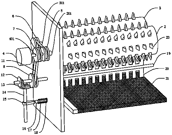
[0037] refer to Figure 2-3 , a sand screening device for construction, which is basically the same as Embodiment 1, the difference is that the first linkage assembly includes a first driving pulley 5 and a first driven pulley 6, and the first driving pulley 5 is connected to the On the outer wall of the three rotating shafts 401, the first driven pulley 6 is connected to one end of the second rotating shaft 301 placed inside the driving cavity, and the first driving pulley 5 is connected to the first driven pulley 6 through the belt 11;

[0038] The rotation of the third rotating shaft 401 drives the first driving pulley 5 to rotate, and the first driving pulley 5 drives the first driven pulley 6 to rotate through the belt 11, so that the first driving pulley 5 and the first driven pulley 6 are respectively Drive the first rotating shaft 201 and the second rotating shaft 301 to rotate together.

Embodiment 3

[0040] refer to Figure 2-3 , a sand screening device for construction, which is basically the same as Embodiment 2, the difference is that the second linkage assembly includes a second driving pulley 7 and a second driven pulley 8, and the second driving pulley 7 and the third The outer wall of the rotating shaft 401 is connected, the second driven pulley 8 is connected with the outer wall of the fourth rotating shaft 9 placed inside the driving cavity, and the second driving pulley 7 is connected with the second driven pulley 8 through the belt 11;

[0041] Dispersing assembly comprises stirring rod 19 and stirring blade 20, and stirring rod 19 is connected with an end that places the fourth rotating shaft 9 inside the screening cavity, and stirring blade 20 is connected on the rod wall of stirring rod 19;

[0042] The stirring blade 20 is a toothed structure, and the distance between the stirring rod 19 and the vibrating sieve plate 21 is half of the width of the stirring b...


PUM


Abstract

The invention discloses a sand screening device for construction, and belongs to the field of architectural engineering. The sand screening device for construction comprises a screening box and a vibrating screen plate, wherein the drive end of a motor is connected with a third rotary shaft; one end, away from the inner side wall of a drive cavity, of a fourth rotary shaft passes through a partition, extends into a screening cavity, and the extending end is connected with a dispersing assembly; one end, away from the third rotary shaft, of a first linking assembly is connected to one end, inside a drive shaft, of a second rotary shaft; one end, away from a rotary rod, of a transmission assembly is connected to the rod wall, inside the drive cavity, of the fourth rotary shaft; and one end,away from a rotary rod, of a reciprocating mechanism is connected to the side wall of the vibrating screen plate. The motor works to drive a first pressure roller and a second pressure roller for pressing sand through the first linking assembly, the dispersing assembly disperses pressed sand onto the vibrating screen plate, and the reciprocating mechanism drives the vibrating screen plate to shakeback and forth to perform sand screening, so that sand screening speed is quickened, and working efficiency of the device is improved.

Description

technical field [0001] The invention relates to the technical field of construction engineering, in particular to a sand screening device for construction. Background technique [0002] Construction engineering refers to engineering entities formed through the construction of various housing buildings and their ancillary facilities and the installation of supporting lines, pipelines, and equipment. Housing construction refers to roofs, beams, walls, foundations, It is a project that forms an internal space and meets the needs of people's production, living, learning, and public activities. Sand screening machine, also known as dry land sand screening ship, sand and gravel separator, is a sand and gravel separation equipment suitable for rivers, reservoirs, and coal yards. It consists of the hull, Composed of frame, reducer, conveyor belt, rotary screen, engine or motor, it is simple in structure, economical and applicable, and easy to operate. It is divided into drum sand sc...

Claims


Application Information

Patent Timeline
Patent Type & Authority Applications(China)
IPC IPC(8): B07B1/28B07B1/42B02C4/08B02C4/42B02C13/02B02C13/28
CPCB02C4/08B02C4/42B02C13/02B02C13/28B07B1/28B07B1/42
Inventor 肖铭陆文婷谢兆良丁一行
Owner 南京市月华路小学
Why Eureka
Try Eureka