Waste plastic melt-extruding device

A melt extrusion and waste plastic technology, applied in the field of waste plastic recycling, can solve the problems of inability to ensure uniform heating, low production efficiency, inability to achieve high-speed operation, etc., to improve the melting rate and melting uniformity, high consistency, Reduce the effect of jitter and resonance

Inactive Publication Date: 2018-05-01
泉州市铭益塑料制品有限公司
View PDF6 Cites 6 Cited by
  • Summary
  • Abstract
  • Description
  • Claims
  • Application Information

AI Technical Summary

Problems solved by technology

This technical solution adopts the form of setting a heater on the screw, and the raw materials are melted and heated during extrusion and drawing. The whole process cannot guarantee uniform heating, and for some plastic materials with high melting temperature, it cannot meet the production needs. In order to ensure the melting of raw materials in the process, high-speed operation cannot be realized, and the production efficiency is low

Method used


Image

  • Waste plastic melt-extruding device
  • Waste plastic melt-extruding device
  • Waste plastic melt-extruding device

Examples


Embodiment 1

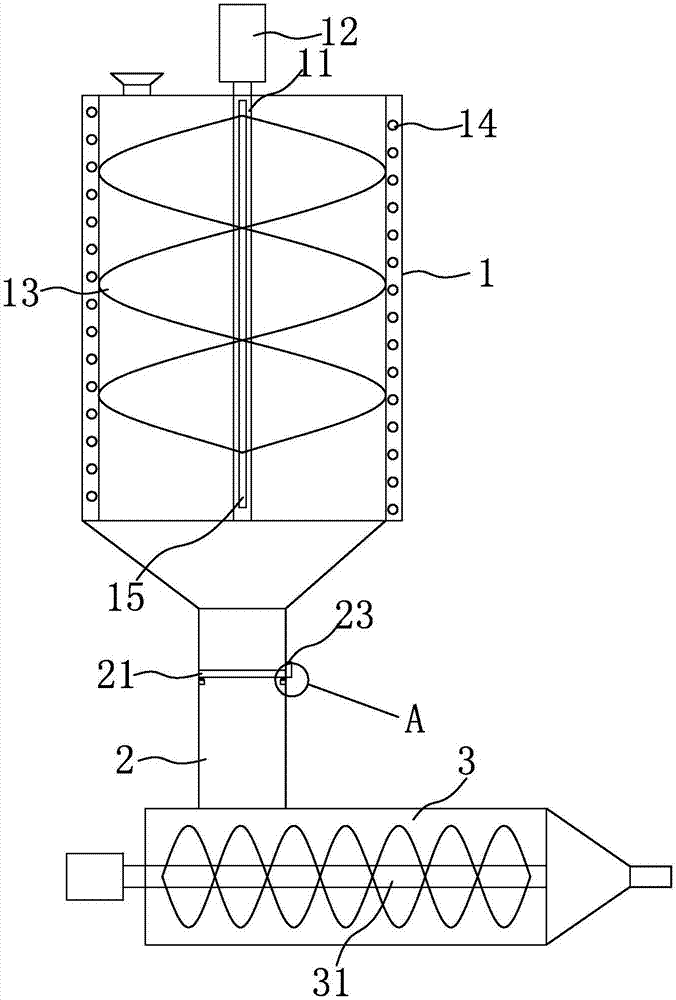
[0019] refer to figure 1 and figure 2 , a waste plastic melting extrusion device, including a melting tank 1, a material tank 2 and an extruding barrel 3 with an extrusion screw 31, the melting tank 1 is surrounded by a heater, and the upper end of the melting tank 1 is provided with a The feed port where the plastic fragments enter has a discharge port below and communicates with the material tank 2, and the lower end of the material tank 2 communicates with the extruding barrel 3. A stirring mechanism is provided in the melting tank 1, and the stirring mechanism includes a set In the stirring shaft 11 in the melting tank 1 and the stirring motor 12 for driving the stirring shaft 11, the stirring shaft 11 is provided with a stirring blade 13; in the present embodiment, the stirring shaft 11 is arranged on the The center of the melting tank 1;

[0020] In this embodiment, the heater includes a spiral electric heating coil 14 and a heating rod 15 arranged on the stirring sha...

Embodiment 2

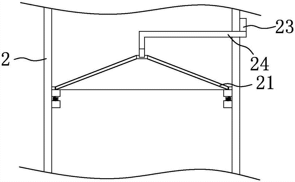
[0023] refer to image 3 , compared with Embodiment 1, the metal filter screen 21 is in the shape of a cone protruding upwards, and the center of the metal filter screen 21 is provided with a connecting rod 24 protruding from the outside of the material tank, and the vibration motor 23 It is fixed on the connecting rod 24 outside the material tank 2; by setting the connecting rod 24, the vibration of the metal filter screen 21 is diffused from the center to the surroundings, and its structure is a cone shape, which can make the material under the action of its own gravity. Slide down on the metal filter screen 21, have enough space to pass through, can not pile up on the metal filter screen 21.

[0024] refer to Figure 4 , Figure 5 , in this embodiment, the melting tank 1 is cylindrical, the stirring shaft 11 is arranged radially of the melting tank 1, and the length of the stirring blade 13 gradually increases from both ends of the stirring shaft 11 to the middle, Betwee...


PUM


Abstract

The invention relates to the field of recycle of waste plastic, in particular to a waste plastic melt-extruding device. The waste plastic melt-extruding device comprises a melting tank, a material tank and an extruding cylinder, wherein the extruding cylinder is provided with an extruding screw; the four sides of the melting tank are each provided with a heater; the upper end of the melting tank is provided with a feeding opening for feeding a waste plastic fragment; the lower portion of the melting tank is provided with a discharging opening and communicates with the material tank; the lowerend of the material tank communicates with the extruding cylinder; a stirring mechanism is arranged inside the melting tank; the stirring mechanism comprises a stirring shaft and a stirring motor, wherein the stirring shaft is arranged inside the melting tank; the stirring motor is used for driving the stirring shaft; the stirring shaft is provided with stirring blades; a metal filter screen is arranged inside the material tank; a peripheral frame of the metal filter screen is arranged inside the material tank; buffering springs are arranged at the joint of the metal filter screen and the material tank; the metal filter screen is connected with a vibrating motor; at least three buffering springs are arranged; and the metal filter screen is in a cone shape protruding upwards.

Description

technical field [0001] The invention relates to the field of waste plastic recycling, in particular to a waste plastic melting extrusion device. Background technique [0002] Most of the existing melt extruders are plastic granules with consistent raw materials. Nowadays, plastic products have been widely used in various fields. With the increasing consumption of plastic products, waste plastics are also increasing. The melting extruder designed for waste gas plastics, such as the Chinese patent CN104890146A with an application date of September 9, 2015, discloses a waste plastic melting device, including a feeding port, a metal cylinder, a conveying roller, a motor, a discharge port, a heating The device also includes a stirrer, a filter device, a filter plate, and a permanent magnet. The upper end of the metal cylinder is provided with a feeding port, and the bottom of the feeding port is provided with a stirrer, and a filter device is installed below the stirrer. A conve...

Claims


Application Information

Patent Timeline
Patent Type & Authority Applications(China)
IPC IPC(8): B29C47/10B29C47/78B29C47/36B29B13/10
CPCB29B13/10B29C48/288B29C48/36B29C48/793
Inventor 庄金龙
Owner 泉州市铭益塑料制品有限公司
Why Eureka
Try Eureka