Spring machine for forming of pulling and pressing rod

The technology of a spring machine and a pressure rod is applied in the field of spring machining, which can solve the problems of low production efficiency and high production cost, and achieve the effects of high production efficiency, simple structure and reasonable design.

Active Publication Date: 2019-08-16
东莞市永强弹簧五金有限公司
View PDF5 Cites 6 Cited by
  • Summary
  • Abstract
  • Description
  • Claims
  • Application Information

AI Technical Summary

Problems solved by technology

[0002] like Figure 5 As shown, the structure of the final finished product lever from one end to the other is: the first bending section 32, the second bending section 33, and the third bending section 34. The traditional production method is to first bend the The raw material is bent for a section, and then the bent workpiece is placed on the stamping equipment for stamping, which requires multiple equipment for processing, which not only has low production efficiency, but also high production costs

Method used


Image

  • Spring machine for forming of pulling and pressing rod
  • Spring machine for forming of pulling and pressing rod
  • Spring machine for forming of pulling and pressing rod

Examples


Embodiment Construction

[0021] In order to enable those skilled in the art to better understand the technical solution of the present invention, the present invention will be described in detail below in conjunction with the accompanying drawings. The description in this part is only exemplary and explanatory, and should not have any limiting effect on the protection scope of the present invention. .

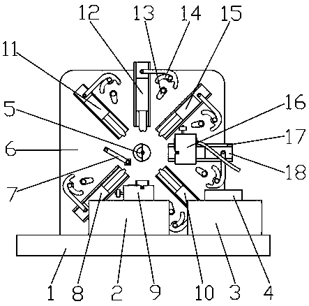
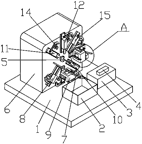
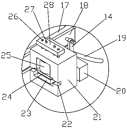
[0022] Such as Figure 1-Figure 5 Shown, the structure of the present invention is: a kind of spring machine that pulls pressure rod molding usefulness, and it comprises base 1 and cabinet 6, and the center of described cabinet 6 is provided with feeding shaft 5, and the front end of described cabinet 6 is positioned at feeding shaft 5 The first cutter seat 8, the first stamping device 9, the second cutter seat 10, the second stamping device 16, the third cutter seat 15, the bending knife seat 12 and the fourth cutter seat 11 are successively arranged around, so The bending tool holder 12 is arranged ...


PUM


Abstract

The invention relates to a spring machine for forming of a pulling and pressing rod. The spring machine comprises a base and a case. A feeding shaft is arranged in the center of the case, a first cutter seat, a first stamping device, a second cutter seat, a second stamping device, a third cutter seat, a bending cutter seat and a fourth cutter seat are sequentially arranged at the front end of thecase and around the feeding shaft, the bending cutter seat is arranged right above the feeding shaft, the first stamping device is arranged right below the feeding shaft; the second stamping device isarranged on the right side of the feeding shaft, the left side of the feeding shaft is provided with a material taking device, the first cutter seat, the second cutter seat, the third cutter seat, the bending cutter seat, the fourth cutter seat, the first stamping device and the second stamping device all slide along the axis of the feeding shaft and are respectively matched with a driving devicearranged on the case, and the first stamping device and the second stamping device are both connected with a hydraulic oil tank arranged on the base. The spring machine is pulling and pressing rod forming equipment which can realize one-time forming and has high production efficiency by utilizing the bending cutter seat and combining with the stamping devices.

Description

technical field [0001] The invention relates to the field of spring machining, in particular to a spring machine for forming a pull bar. Background technique [0002] Such as Figure 5 As shown, the structure of the final finished product lever from one end to the other is: the first bending section 32, the second bending section 33, and the third bending section 34. The traditional production method is to first bend the The raw material is bent for a section, and then the bent workpiece is placed on the stamping equipment for stamping, which requires multiple equipment for processing, which not only has low production efficiency, but also high production cost. Contents of the invention [0003] The object of the present invention is to provide a forming device with simple structure and reasonable design, which can realize one-time forming by using a bending knife seat combined with a stamping device, and has high production efficiency. [0004] In order to achieve the ab...

Claims


Application Information

Patent Timeline
Patent Type & Authority Applications(China)
IPC IPC(8): B21F1/00B21F11/00B21F23/00
CPCB21F1/00B21F1/004B21F11/00B21F23/00
Inventor 吴志富
Owner 东莞市永强弹簧五金有限公司
Why Eureka
Try Eureka