Workpiece polishing robot

A technology for robots and workpieces, applied in the field of robots, can solve the problems of continuous movement of workers and uneven grinding, and achieve the effect of saving manpower, uniform grinding and easy grinding.

Active Publication Date: 2019-08-16
GUANGDONG POLYTECHNIC NORMAL UNIV
View PDF5 Cites 4 Cited by
  • Summary
  • Abstract
  • Description
  • Claims
  • Application Information

AI Technical Summary

Problems solved by technology

[0003] In order to overcome the shortcomings of the current concave plate grinding relying on manual work, which requires the staff to move continuously and the grinding is uneven, the technical problem to be solved is: to provide a workpiece grinding and polishing robot that can realize automatic grinding and uniform grinding

Method used


Image

  • Workpiece polishing robot
  • Workpiece polishing robot
  • Workpiece polishing robot

Examples


Embodiment 1

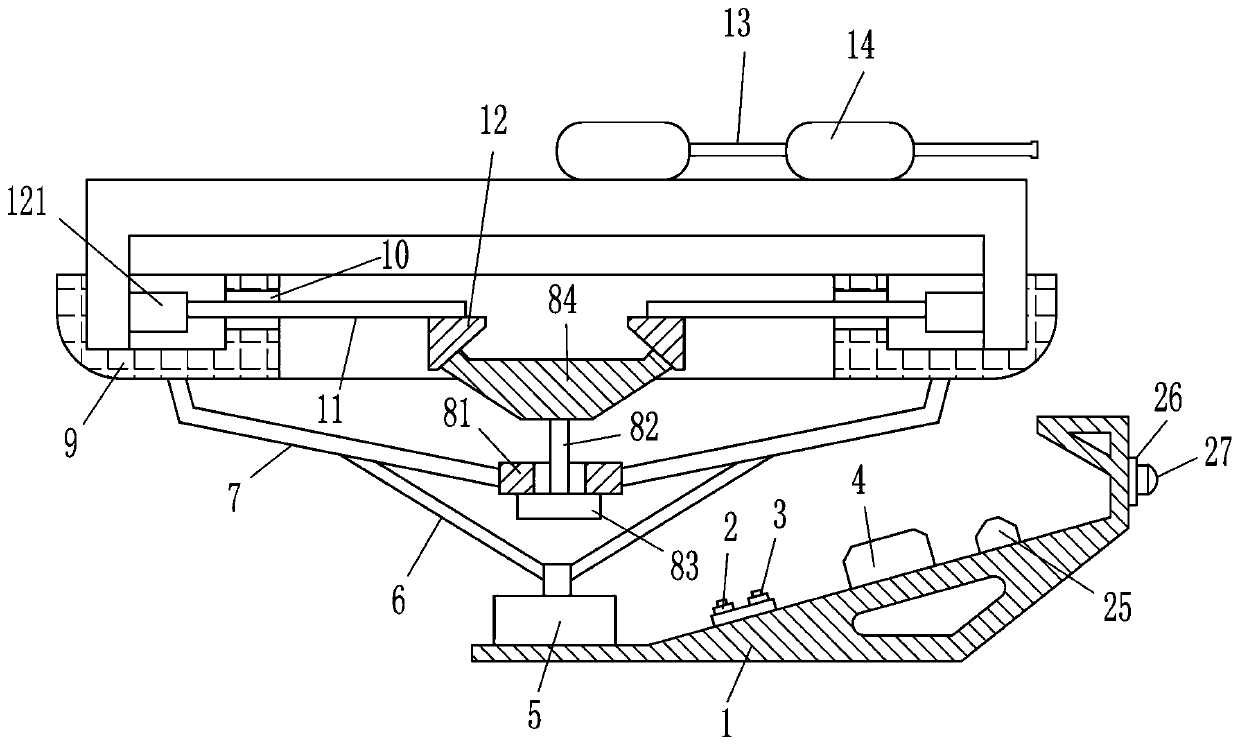
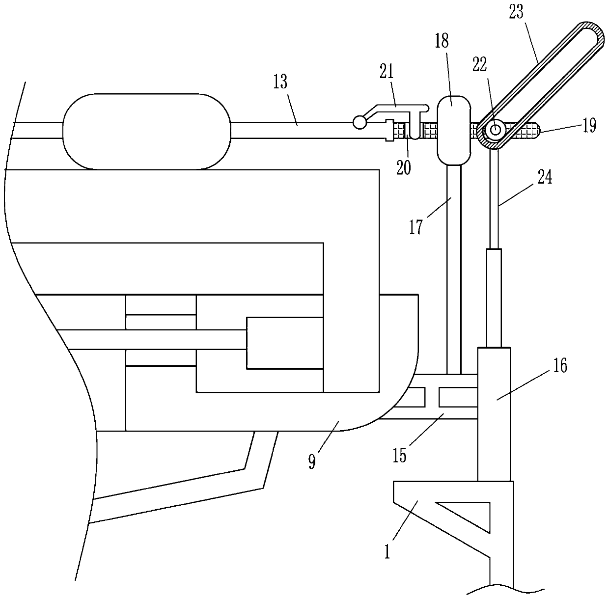
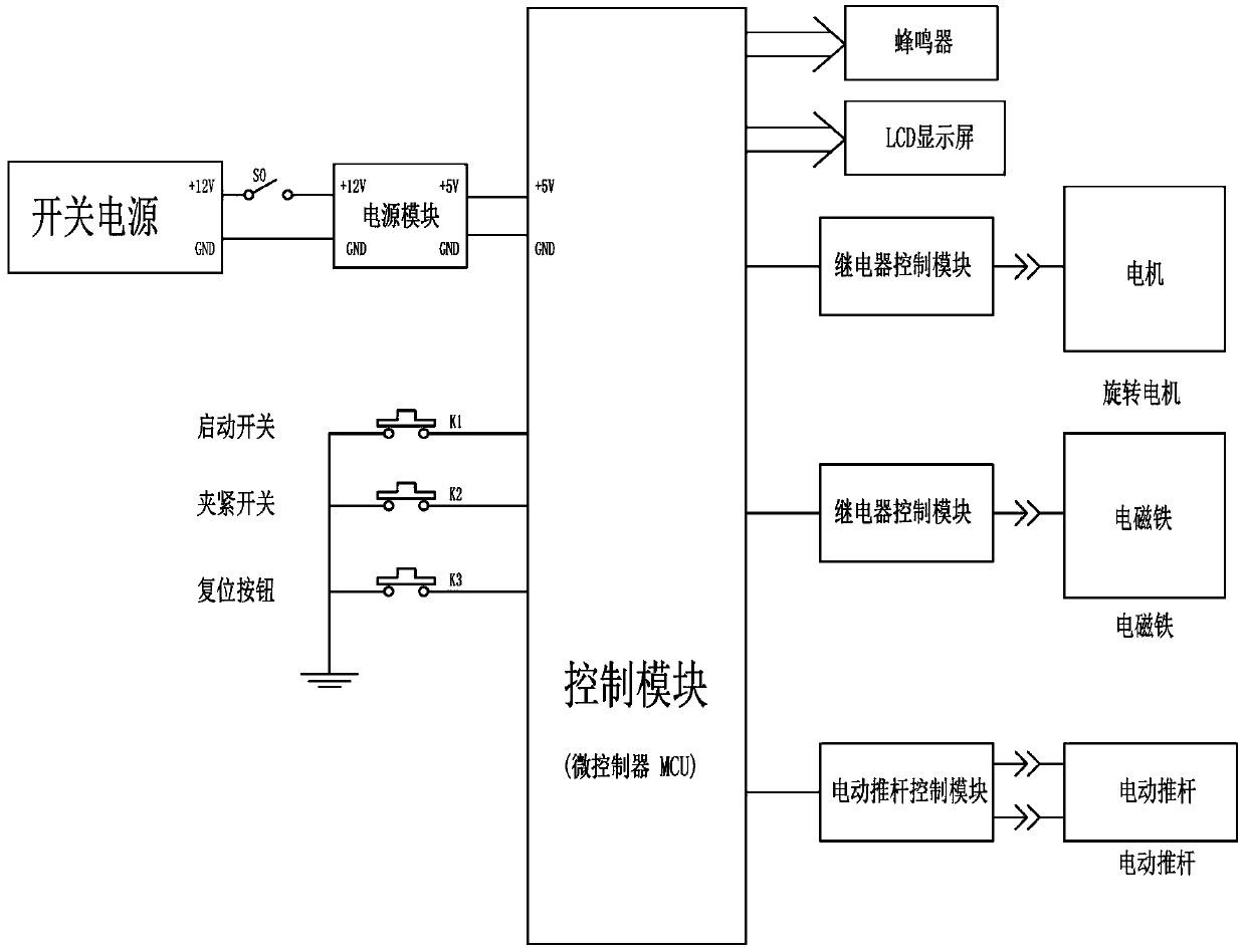
[0019] A workpiece grinding and polishing robot, such as Figure 1-3 As shown, it includes a fixed frame 1, a start switch 2, a clamp switch 3, a control box 4, a rotating motor 5, a connecting rod 6, a support rod 7, a clamping device 8, a ring frame 9, a moving rod 11, and a triangular block 12 , clamping block 121, grinding rod 13 and grinding block 14, start switch 2 and clamping switch 3 are installed on the left side of the inner bottom wall of the fixed frame 1, the starting switch 2 is located on the left side of the clamping switch 3, the inner bottom of the fixed frame 1 A control box 4 is installed in the middle of the wall, and the control box 4 includes a switching power supply, a power module and a control module. A rotating motor 5 is installed on the left side of the inner bottom wall of the fixed frame 1. The rotating motor 5 is located on the left side of the start switch 2. The rotating motor 5 The left and right sides of the output shaft of the output shaft...

Embodiment 2

[0021] A workpiece grinding and polishing robot, such as Figure 1-3 As shown, it includes a fixed frame 1, a start switch 2, a clamp switch 3, a control box 4, a rotating motor 5, a connecting rod 6, a support rod 7, a clamping device 8, a ring frame 9, a moving rod 11, and a triangular block 12 , clamping block 121, grinding rod 13 and grinding block 14, start switch 2 and clamping switch 3 are installed on the left side of the inner bottom wall of the fixed frame 1, the starting switch 2 is located on the left side of the clamping switch 3, the inner bottom of the fixed frame 1 A control box 4 is installed in the middle of the wall, and the control box 4 includes a switching power supply, a power module and a control module. A rotating motor 5 is installed on the left side of the inner bottom wall of the fixed frame 1. The rotating motor 5 is located on the left side of the start switch 2. The rotating motor 5 The left and right sides of the output shaft of the output shaft...

Embodiment 3

[0024] A workpiece grinding and polishing robot, such as Figure 1-3As shown, it includes a fixed frame 1, a start switch 2, a clamp switch 3, a control box 4, a rotating motor 5, a connecting rod 6, a support rod 7, a clamping device 8, a ring frame 9, a moving rod 11, and a triangular block 12 , clamping block 121, grinding rod 13 and grinding block 14, start switch 2 and clamping switch 3 are installed on the left side of the inner bottom wall of the fixed frame 1, the starting switch 2 is located on the left side of the clamping switch 3, the inner bottom of the fixed frame 1 A control box 4 is installed in the middle of the wall, and the control box 4 includes a switching power supply, a power module and a control module. A rotating motor 5 is installed on the left side of the inner bottom wall of the fixed frame 1. The rotating motor 5 is located on the left side of the start switch 2. The rotating motor 5 The left and right sides of the output shaft of the output shaft ...


PUM


Abstract

The invention relates to a robot, in particular to a workpiece polishing robot. The workpiece polishing robot can realize automatic polishing and uniform polishing. The workpiece polishing robot comprises a fixed frame, a starting switch, a clamping switch, a control box, a rotating motor, a connecting rod, a support rod, a clamping device, an annular frame, a movable rod, a triangular block and the like; the starting switch and the clamping switch are mounted on the left side of the bottom wall in the fixed frame; the starting switch is positioned on the left side of the clamping switch; thecontrol box is mounted in middle of the bottom wall in the fixed frame; and the control box comprises a switch power supply, a power supply module and a control module. The workpiece polishing robot achieves the effects of automatic polishing and uniform polishing, can fix workpieces through arrangement of the clamping device to achieve polishing of the workpieces, and can drive the workpieces torotate through the rotating motor without needing to shift the workpieces by workers during polishing to save the manpower.

Description

technical field [0001] The invention relates to a robot, in particular to a workpiece grinding and polishing robot. Background technique [0002] Now the use of concave plates in the field of construction is becoming more and more widespread. Now after the concave plate is made, the surface needs to be polished. Due to the large surface area of ​​the concave plate, it is generally necessary to manually polish it with grinding tools. At the same time, it is necessary to make a circular motion around the concave shape, which requires more manpower for grinding, which makes the staff extremely tired, and the grinding is uneven. Contents of the invention [0003] In order to overcome the disadvantages that the current concave plate grinding relies on manual work, the staff needs to move continuously, and the grinding is uneven. The technical problem to be solved is: to provide a workpiece grinding and polishing robot that can realize automatic grinding and even grinding. [0...

Claims


Application Information

Patent Timeline
Patent Type & Authority Applications(China)
IPC IPC(8): B24B19/00B24B41/06B24B47/12B24B51/00B24B47/16B24B55/00
CPCB24B19/009B24B41/06B24B47/12B24B47/16B24B51/00B24B55/00
Inventor 王晓军
Owner GUANGDONG POLYTECHNIC NORMAL UNIV
Why Eureka
Try Eureka