Cylindrical iron rod grinding equipment

A cylindrical iron rod technology, applied in the field of cylindrical iron rod grinding equipment, can solve the problems of low working efficiency and uneven grinding of iron rods, and achieve the effect of facilitating work, improving work efficiency and ensuring continuous operation

Pending Publication Date: 2021-02-23
李统
View PDF6 Cites 5 Cited by
  • Summary
  • Abstract
  • Description
  • Claims
  • Application Information

AI Technical Summary

Problems solved by technology

[0005] In order to overcome the shortcomings of low work efficiency and uneven grinding of manual grinding iron rods, the technical problem is to provide a cylindrical iron rod grinding equipment that can realize automatic feeding, automatic grinding and uniform grinding of iron rods

Method used


Image

  • Cylindrical iron rod grinding equipment
  • Cylindrical iron rod grinding equipment
  • Cylindrical iron rod grinding equipment

Examples


Embodiment 1

[0064] A cylindrical iron rod grinding equipment, such as figure 1 , figure 2 , image 3 and 6 As shown, it includes a base plate 1, a motor 2, a first circular gear 3, a rotating mechanism 4, a lifting mechanism 5 and an intermittent feeding mechanism 8, the bottom plate 1 is provided with a motor 2 on the front right side of the top, and the output shaft of the motor 2 is provided with a second gear. A circle gear 3, base plate 1 top right side is provided with rotating mechanism 4, and rotating mechanism 4 is on the motor 2 right side, and rotating mechanism 4 top is provided with lifting mechanism 5, and base plate 1 top left side is provided with intermittent feeding mechanism 8.

[0065] When people need to polish the rusty iron rod, put the iron rod on a certain part of the intermittent feeding mechanism 8, then start the motor 2, the output shaft of the motor 2 drives the first round gear 3 to rotate, and the first round gear 3 drives The rotating mechanism 4 and the...

Embodiment 2

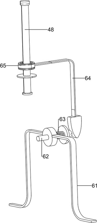
[0073] On the basis of Example 1, such as Figure 4 As shown, a pressure-assist mechanism 6 is also included, and the pressure-assist mechanism 6 includes a fourth bracket 61, a small cylinder 62, a spring 63, a push rod 64 and a second bearing 65, and the right front part of the top of the bottom plate 1 is provided with a fourth bracket 61, the fourth bracket 61 is on the left side of the first bracket 41, and the middle of the top of the fourth bracket 61 is slidingly provided with a small cylinder 62, and a spring 63 is arranged between the right part of the small cylinder 62 and the right side of the fourth bracket 61, and 63 sets of springs On the outside of the small cylinder 62, the lower part of the rotating shaft 48 is provided with a second bearing 65, the second bearing 65 is on the upper side of the second bracket 413, and the right side of the second bearing 65 is provided with a push rod 64, and the push rod 64 and the small cylinder 62 are extrusion fit .

[0...

Embodiment 3

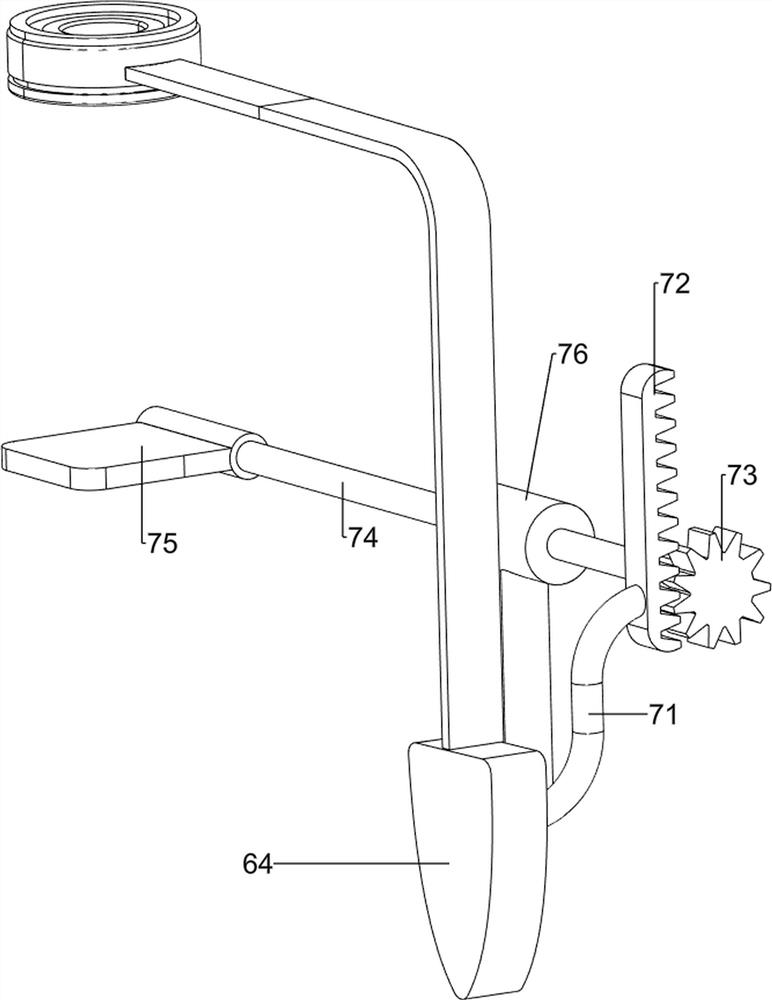
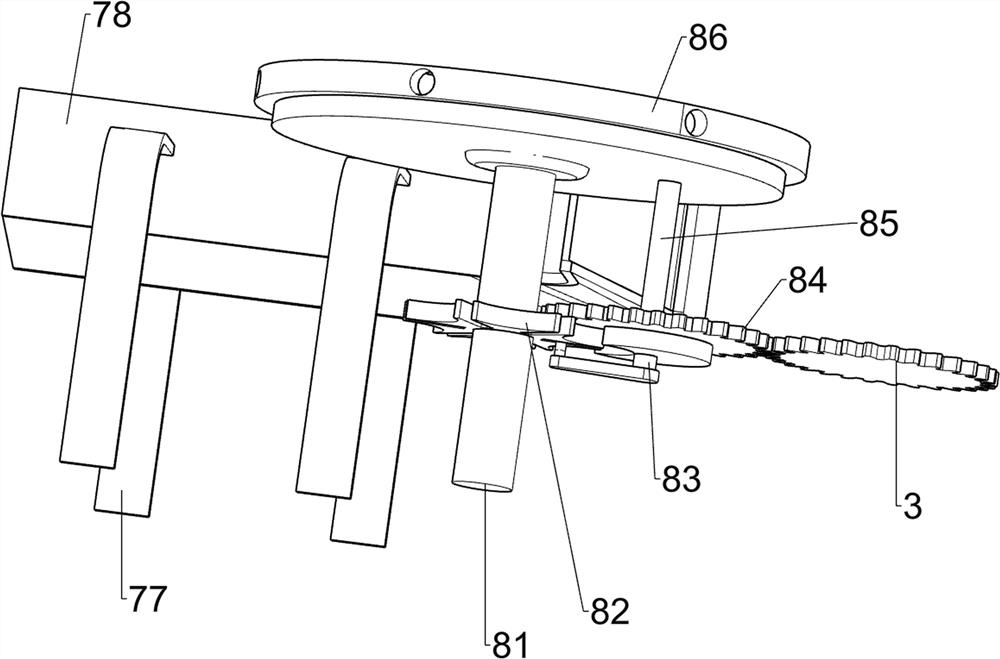
[0076] On the basis of Example 2, such as Figure 5-6 As shown, it also includes a rotary push mechanism 7, and the rotary push mechanism 7 includes a fourth pole 71, a rack 72, an eighth round gear 73, a rotating rod 74, a rotating block 75, a fifth bracket 76, a sixth The support 77 and the discharge frame 78, the push rod 64 rear side is provided with the fourth pole 71, the fourth pole 71 rear side is provided with the rack 72, the fourth support 61 top rear side is provided with the fifth support 76, the fifth The rotation type of support 76 tops is provided with turning bar 74, and turning bar 74 left ends is provided with turning block 75, and turning block 75 is above the second pillar 81, and turning bar 74 right-hand ends is provided with the 8th round gear 73, and the 8th round gear 73 is connected with tooth. The strips 72 are mutually engaged, and the left, rear, left, and right sides of the bottom plate 1 top are provided with a sixth bracket 77, and a discharge ...


PUM


Abstract

The invention relates to grinding equipment, in particular to cylindrical iron rod grinding equipment. The cylindrical iron rod grinding equipment can achieve automatic feeding, automatic grinding anduniform grinding of iron rods. The cylindrical iron rod grinding equipment comprises a bottom plate, a motor arranged on one side of the top of the bottom plate, a first circular gear arranged on anoutput shaft of the motor, a rotating mechanism arranged on one side of the top of the bottom plate and located on one side of the motor, a lifting mechanism arranged at the top of the rotating mechanism, and an intermittent feeding mechanism arranged on the side, away from the rotating mechanism, of the top of the bottom plate. Through cooperation of the rotating mechanism, the lifting mechanismand the intermittent feeding mechanism, automatic feeding and automatic grinding of the iron rods can be achieved, the peripheries of the iron rods can be ground in an all-around mode, and the workingefficiency of people is improved.

Description

technical field [0001] The invention relates to a grinding device, in particular to a cylindrical iron rod grinding device. Background technique [0002] Hardware refers to traditional hardware products, including five metals including gold, silver, copper, iron and tin, which can be made into various artworks or metal devices after manual processing. Now people use hardware widely in their lives. , such as hardware tools, hardware parts, hardware materials for construction and hardware supplies for daily use. Iron rods are common hardware in daily life, and iron rods are prone to rust when exposed to the air for a long time. [0003] Rusty iron rods are unsightly and will stick to people's hands when they are used. If there is a wound on the hand, it is easy to be infected with tetanus. If you get tetanus, you must get vaccinated in time. cause death. Therefore, it is necessary to polish the rusty iron rods. According to the existing technology, most of the iron rods are...

Claims


Application Information

Patent Timeline
Patent Type & Authority Applications(China)
IPC IPC(8): B24B27/033B24B5/04B24B27/00B24B41/00B24B41/06B24B47/12B24B47/16
CPCB24B27/033B24B5/047B24B27/0076B24B27/0023B24B47/12B24B47/16B24B41/067B24B41/005
Inventor 李统
Owner 李统
Why Eureka
Try Eureka