
Preliminary outer surface layer grinding treatment equipment for lens processing

A technology for lens processing and processing equipment, applied in metal processing equipment, grinding/polishing equipment, grinding machines, etc., can solve problems such as damage to the lens, the water temperature cannot reach a constant temperature, and the quality of the lens is reduced, and achieves the effect of improving the effect.

Inactive Publication Date: 2022-03-01
江西超联光电科技有限公司
View PDF1 Cites 4 Cited by
  • Summary
  • Abstract
  • Description
  • Claims
  • Application Information

AI Technical Summary

Problems solved by technology

[0004] The lens grinding device grinds the lens through the grinding wheel, and the lens can be cleaned while grinding, but the cleaning water temperature cannot achieve a constant temperature effect. If the water temperature is too high or too low, the lens will be damaged, resulting in a decline in the quality of the lens. Now we are developing a preliminary outer layer grinding equipment for lens processing that can realize the constant temperature of the cleaning water temperature.

Method used


Image

  • Preliminary outer surface layer grinding treatment equipment for lens processing
  • Preliminary outer surface layer grinding treatment equipment for lens processing
  • Preliminary outer surface layer grinding treatment equipment for lens processing

Examples


Embodiment 1

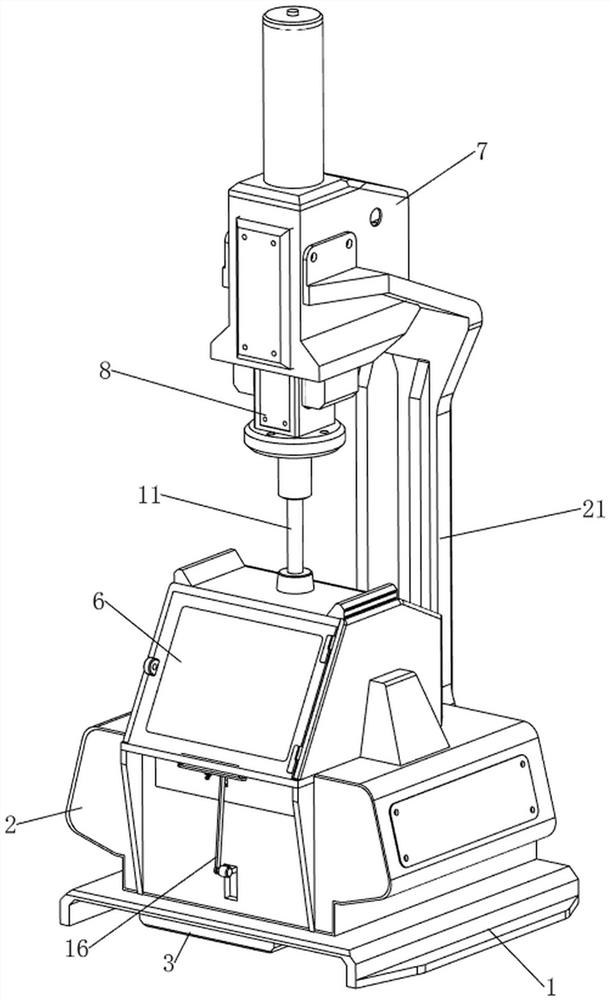
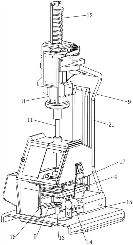
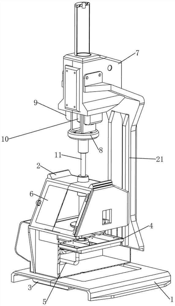
[0041] A kind of preliminary outer layer grinding treatment equipment for lens processing, such as Figure 1-13 As shown, it includes a base 1, a first shell 2, a first bracket 21, a fixed plate 4, a water pipe 5, a cover plate 6, a second shell 7, a sliding frame 8, a first slide rail 9, a driving motor 10, and a rotating shaft 11 , grinding mechanism 12, bearing mechanism 13, flushing mechanism 14 and constant temperature mechanism 15, the first casing 2 is arranged in the middle of the top of the base 1, the inside of the first casing 2 is provided with strip grooves on the front and rear sides, and on the front of the first casing 2 The side sliding type is connected with a cover plate 6, and the cover plate 6 is made of glass, which is convenient for people to observe the process of lens polishing. The rear side of the top of the base 1 is welded with a first bracket 21, and the upper part of the first bracket 21 is welded with a second shell 7. The left and right sides o...

Embodiment 2

[0048] On the basis of Example 1, such as figure 1 , figure 2 , Figure 14 , Figure 15 , Figure 16 and Figure 17 As shown, a clamping mechanism 16 is also included for clamping the cover plate 6. The clamping mechanism 16 includes a third connecting rod 161, a fourth connecting rod 162, a second rotating rod 163, and a fifth connecting rod 164. and the clamping block 165, the clamping block 165 is slidably connected in the middle of the front side of the first shell 2, and the clamping block 165 is used for clamping and limiting the cover plate 6, and the bottom of the clamping block 165 is connected with the fifth connecting rod 164 in a rotatable manner. The middle of the lower side of the front part of the housing 2 is rotationally connected with a second rotating rod 163, and the front side of the second rotating rod 163 is rotationally connected with the fifth connecting rod 164. A fourth connecting rod 162 is rotatably connected between the front side of the thr...


PUM


Abstract

The invention relates to outer surface layer grinding treatment equipment, in particular to preliminary outer surface layer grinding treatment equipment for lens processing. The technical problem to be solved is to provide the preliminary outer surface layer grinding treatment equipment for lens processing, which can realize constant temperature of cleaning water. According to the technical scheme, the preliminary outer surface layer grinding treatment equipment for lens machining comprises a base, a first shell, a cover plate, a first support, a second shell and the like, the first shell is arranged in the middle of the top of the base, strip-shaped grooves are formed in the front side and the rear side in the first shell, and the cover plate is slidably connected to the upper side of the front portion of the first shell; a first support is arranged on the rear side of the top of the base. Through the detection effect of the temperature sensor on the water temperature, the water temperature can be kept between two temperature values, and the constant temperature effect on water can be achieved.

Description

technical field [0001] The invention relates to an outer layer grinding treatment device, in particular to a preliminary outer layer grinding treatment device for lens processing. Background technique [0002] In the process of making lenses, it is necessary to perform preliminary grinding on the outer layer of the lens. Now there are various grinding methods and grinding machines. Each grinding machine has its advantages and disadvantages. Grinding the burr on the surface of the lens can be Improve the smoothness of the lens and improve the gloss of the lens. [0003] The patent application number is CN201921556591.5 A lens grinding device, including a frame, the bottom of the frame is equipped with a rotating shaft, and a rotating base is coaxially installed on the rotating shaft, and the rotating base can rotate around the The shaft rotates, and the surface of the rotating base is provided with a lens groove for positioning the lens. The bottom of the lens groove is an u...

Claims


Application Information

Patent Timeline
Patent Type & Authority Applications(China)
IPC IPC(8): B24B13/00B24B55/02B24B27/00B24B13/005B24B41/02B24B49/14B24B55/06
CPCB24B13/00B24B55/02B24B27/0046B24B13/0055B24B41/02B24B49/14B24B55/06
Inventor 李燮民黄学飞
Owner 江西超联光电科技有限公司
Learn More