Automobile bracket with embedding part and die-casting die for forming automobile bracket

A technology for die-casting molds and automobiles, which is applied in vehicle parts, control devices, transportation and packaging, etc., can solve the problems of low porosity, difficult mold ejection of brackets, and many pores, and achieves reduced porosity and good quality of bracket products. Effect

Active Publication Date: 2019-08-16
NINGBO HUASHUO MOLDING & MACHINE
View PDF10 Cites 4 Cited by
  • Summary
  • Abstract
  • Description
  • Claims
  • Application Information

AI Technical Summary

Problems solved by technology

[0002] The assembly of automobile brackets with transmission shafts and other parts requires strong load-bearing capacity and good sealing performance of the brackets, so as to meet the use requirements of the brackets. The production capacity requirements of the brackets are large, and most brackets are formed by die-casting molds. Existing The problems existing in the molding of the bracket are: it is difficult to release the mold at the through hole of the bracket, and there are many air holes on the circumference of the through hole. After the through hole of the formed bracket is processed, the internal air holes are exposed. After the through hole is inserted, there will be problems such as oil lea

Method used


Image

  • Automobile bracket with embedding part and die-casting die for forming automobile bracket
  • Automobile bracket with embedding part and die-casting die for forming automobile bracket
  • Automobile bracket with embedding part and die-casting die for forming automobile bracket

Examples


Embodiment Construction

[0036] The technical solutions of the present invention will be further described in detail below in conjunction with the drawings and specific embodiments, but the present invention is not limited to these embodiments.

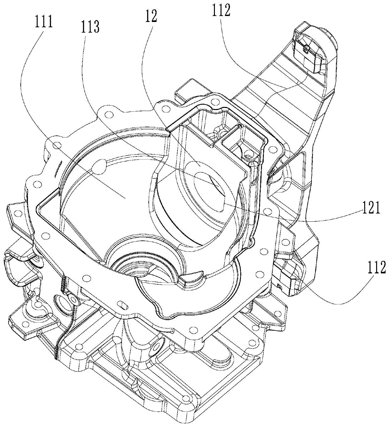
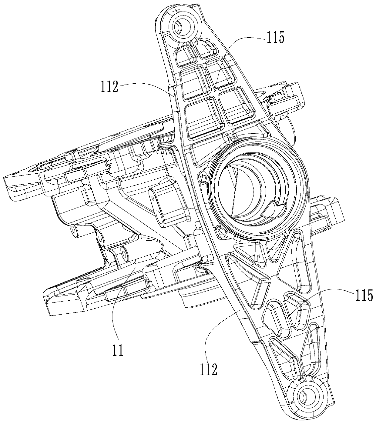
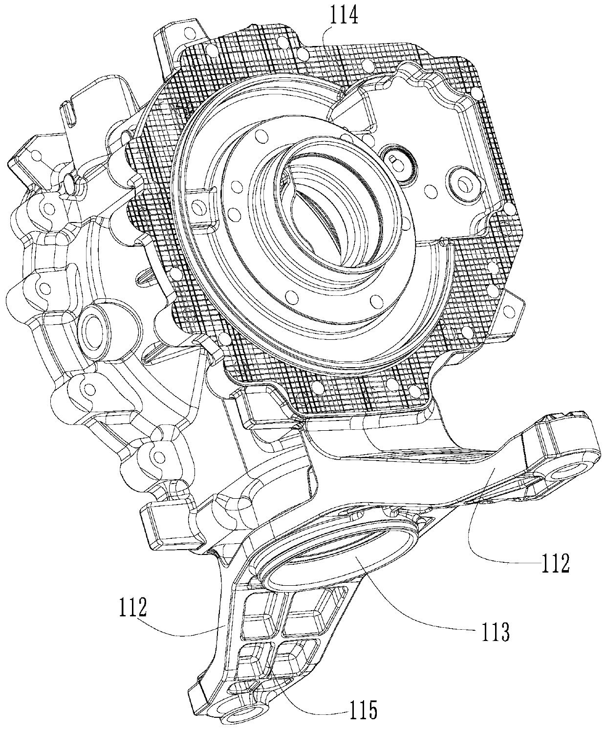
[0037] Such as Figure 1-11 As shown, an automobile bracket with an insert includes: a body 11 and an insert 12 .

[0038] The main body 11 is provided with an installation cavity 111 on the upper part of the main body 11, and the side of the main body 11 protrudes to form two brackets 112; Communication; the insert 12 is set in the through hole 113 and is on the side close to the installation cavity 111 ; the insert 12 is provided with a positioning surface 121 . The insert 12 is ring-shaped, and the positioning surface 121 is on the inner ring surface, which is used for the positioning of the insert 12 fixed in the mold; and the inner ring surface of the insert 12 is provided with 0 A slope of ~3 degrees means that the inner diameter of the inner ring sur...


PUM


Abstract

The invention discloses an automobile bracket with an embedding part and a die-casting die for forming the automobile bracket. The automobile bracket comprises a body and the embedding part, a mounting cavity is formed in the upper part of the body, and the side face of the body protrudes to form two supports; a through hole is formed in the side face of the body and located between the two supports, and the through hole communicates with the mounting cavity; the embedding part is arranged in the through hole and located on the side close to the mounting cavity; the embedding part is providedwith a positioning surface. The die-casting die comprises a fixed die assembly, a movable die assembly, a core pulling assembly, a casting assembly, an ejecting assembly and a supporting assembly, wherein the core pulling assembly comprises a front sliding block, a rear sliding block, a left sliding block and a right sliding block, and a die cavity for forming the automobile bracket is defined bythe front sliding block, the rear sliding block, the left sliding block, the right sliding block, a first cavity and a second cavity; an embedding pin is arranged in the left sliding block, one end ofthe embedding pin stretches into the die cavity, and the embedding pin is sleeved with the embedding part; after the automobile bracket is formed, the embedding part and the automobile bracket are connected into a whole. The automobile bracket with the embedding part and the die-casting die for forming the automobile bracket have the advantages that the automobile bracket is low in porosity, andthe die structure arrangement is reasonable.

Description

technical field [0001] The invention relates to the technical field of die-casting molds, in particular to an automobile bracket with inserts and a die-casting mold for forming the bracket. Background technique [0002] The assembly of automobile brackets with transmission shafts and other parts requires strong load-bearing capacity and good sealing performance of the brackets, so as to meet the use requirements of the brackets. The production capacity requirements of the brackets are large, and most brackets are formed by die-casting molds. Existing The problems existing in the molding of the bracket are: it is difficult to release the mold at the through hole of the bracket, and there are many air holes on the circumference of the through hole. After the through hole of the formed bracket is processed, the internal air holes are exposed. After the through hole is inserted, problems such as oil leakage and gaps will occur, so the customer's requirements cannot be met, and t...

Claims


Application Information

Patent Timeline
IPC IPC(8): B60K17/24B22D17/22B22D17/24B22D19/00
CPCB22D17/22B22D17/24B22D19/00B60K17/24
Inventor 王洪彪旷鑫文蔡朝新张正来贺宇波张太鑫韩建军凌五龙严海波佘昌菊
Owner NINGBO HUASHUO MOLDING & MACHINE
Why Eureka
Try Eureka