Frame-shaped truss wing beam dual-beam variable pitch single-film flow-converging wing surface flapping wing

A technology of wing beams and trusses, applied in the field of aircraft, can solve the problems of unfavorable flapping wing flight, heavy weight, etc., and achieve the effect of simple conversion of pitch unequal distances

Inactive Publication Date: 2019-08-16
黄双玉
View PDF0 Cites 0 Cited by
  • Summary
  • Abstract
  • Description
  • Claims
  • Application Information

AI Technical Summary

Problems solved by technology

[0008] With the wing skeleton including the spar and wing rib frame, the skin is another problem, that is, it is required to have a certain degree of ductility and elastici

Method used


Image

  • Frame-shaped truss wing beam dual-beam variable pitch single-film flow-converging wing surface flapping wing
  • Frame-shaped truss wing beam dual-beam variable pitch single-film flow-converging wing surface flapping wing
  • Frame-shaped truss wing beam dual-beam variable pitch single-film flow-converging wing surface flapping wing

Examples


Embodiment Construction

[0032] The implementation of the present invention will be further illustrated (described) below in conjunction with the accompanying drawings.

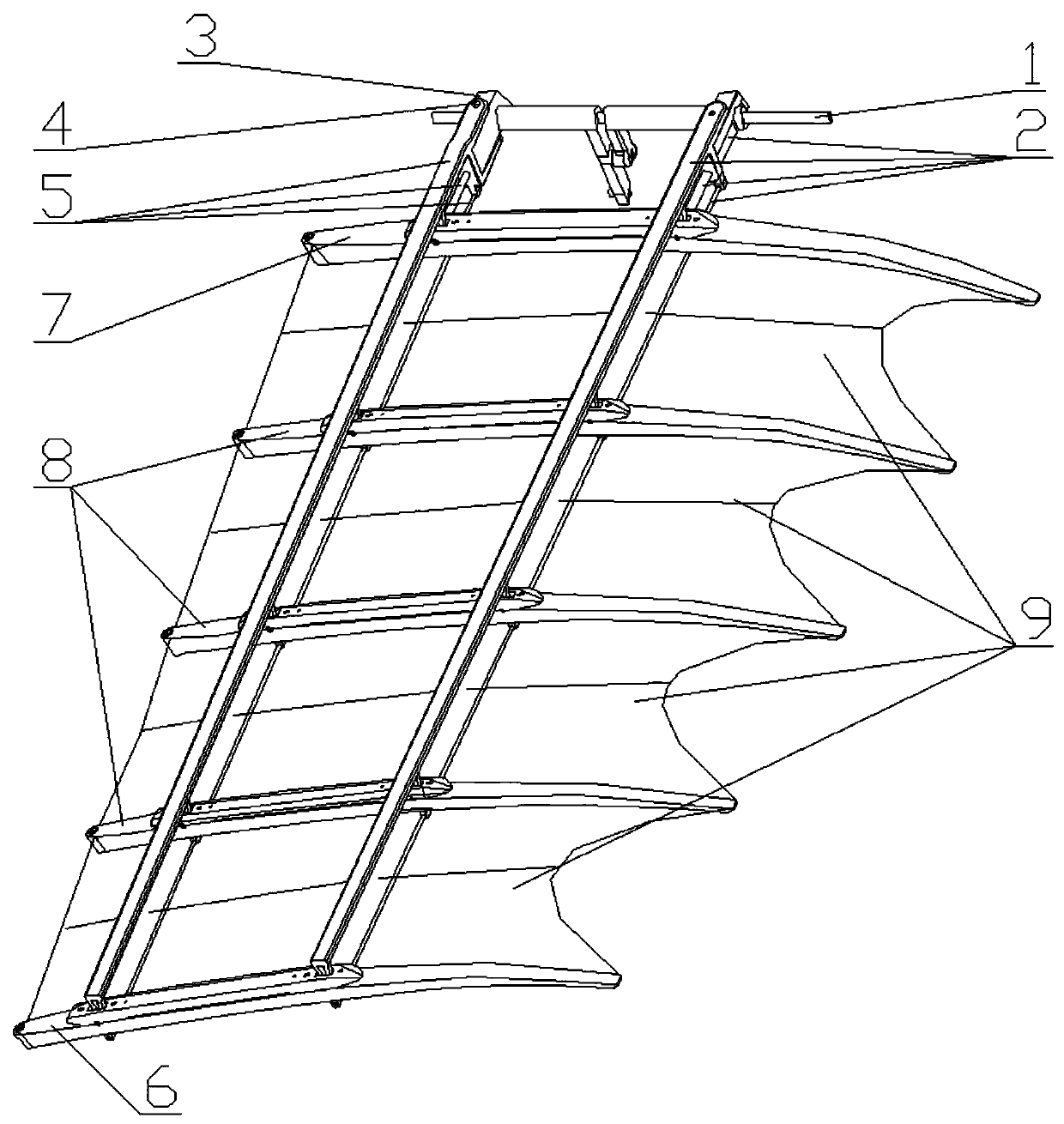
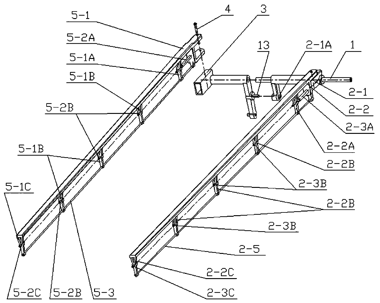
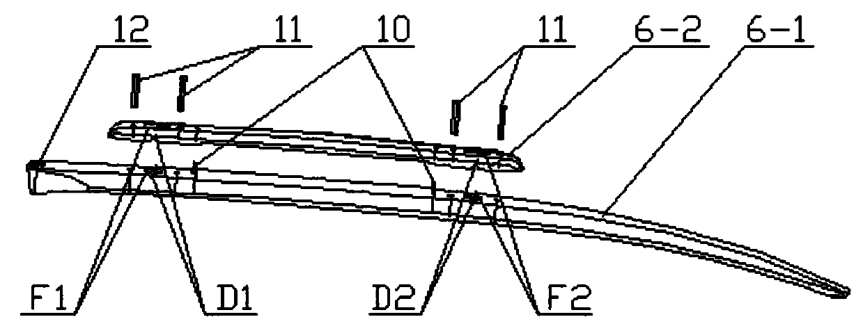
[0033] Frame-shaped truss spar double-girder variable-pitch single-membrane converging airfoil fluttering wing, including the flapping wing main shaft (1); bearing truss spar components (2), floating spar seat (3), pin shaft (4), floating Truss spar parts (5), wing end rib frames (6), wing root rib frames (7), spacer rib frames (8), single-membrane confluence airfoil (9);

[0034] The load-bearing truss spar part (2) includes a load-bearing spar seat (2-1), a load-bearing truss spar (2-2), a load-bearing beam mandrel root section (2-3A), and a load-bearing beam mandrel (2-3A). 3B), the end section of the load-bearing beam mandrel (2-3C), the lower truss (2-4), each piece is assembled into an integral frame-shaped truss firmware; the load-bearing truss wing beam (2-2) is provided with comb teeth type struts (2-2A), the center of the ...


PUM


Abstract

The invention relates to a frame-shaped truss wing beam dual-beam variable pitch single-film flow-converging wing surface flapping wing, and belongs to the technical field of air vehicles. A multi-degree-of-freedom space quadrangle is composed of a flapping wing main shaft 1, a bearing truss wing beam member 2, a floating wing beam seat 3, a floating truss wing beam member 5 and a wing end wing rib frame 6; the floating wing beam seat 3 performs leading flapping around the flapping wing main shaft 1 fixedly connected with a machine body, and the bearing truss wing beam member 2 performs lag follow-up; when flapping wing pitching switching is carried out, the floating truss wing beam member 5 swings front and back in a narrow range around a hinge pin 4 under the limit of the wing end wing rib frame 6; a wing root wing rib frame 7 and a plurality of (in the scheme the number is three) spaced wing rib frames 8 are connected between dual beams in a spanning mode and are limited at the positions of comb-tooth-shaped supporting rods of all wing beams and move following the beams to form pitch angles gradually varied in the wing unfolding direction; and a single-film wing surface 9 is arranged on a center zone of the wing beams and is combined with all the spaced wing rib frames to form four efficient lift-drag ratio wing surfaces which have geometric properties of flow guiding, converging and extruding airflow.

Description

[0001] Technical field [0002] The invention relates to a flapping wing with a frame-shaped truss wing beam, double beams, single-membrane converging airfoil, and belongs to the technical field of aircraft. Background technique [0003] The high-lift mechanism and dexterity of flying birds and insects in nature are related to the complex movement patterns of their wings. It is very difficult for people to realize such complex movement patterns through mechanical structures. [0004] Focusing on the topic of bionic flapping-wing aircraft, controlled-flying flapping-wing aircraft have been developed at home and abroad, but none of them has reached the level of practicality. [0005] In the army discussing the topic of flapping wing aircraft, the rising stage of the wing is often regarded as a burden, and it is always trying to reduce drag, such as setting a one-way air valve type wing surface, shrinking and folding wings, and rising wings on the facade ( Horizontal axis rotati...

Claims


Application Information

Patent Timeline
IPC IPC(8): B64C33/02B64C3/18
CPCB64C3/18B64C3/182B64C3/187B64C33/02
Inventor 黄双玉
Owner 黄双玉
Why Eureka
Try Eureka