
Installation structure of horizontal wrapping machine push plate driving oil cylinders and push plate driving device

A technology for driving oil cylinders and installation structures, applied in packaging, packaging machines, transportation and packaging, etc., can solve the problems of the overall length of the main engine becoming longer, increasing the cost of use, uneven force, etc., to improve service life, save costs, The effect of reducing the failure rate

Pending Publication Date: 2019-08-16
ZHENGZHOU XIELI CONSTR EQUIP
View PDF0 Cites 0 Cited by
  • Summary
  • Abstract
  • Description
  • Claims
  • Application Information

AI Technical Summary

Problems solved by technology

The push plate drive cylinder body of this installation structure protrudes from the rear end face of the main frame, resulting in the overall length of the main machine being longer and requiring a larger space for installation, which increases the cost of use. The push plate drive cylinder of this type of horizontal baler is designed in a single piece. When doing work in motion, it is distributed from one stress point to the surrounding. When compressing and shearing materials, it is easy to cause uneven stress (such as figure 1 )

Method used


Image

  • Installation structure of horizontal wrapping machine push plate driving oil cylinders and push plate driving device
  • Installation structure of horizontal wrapping machine push plate driving oil cylinders and push plate driving device
  • Installation structure of horizontal wrapping machine push plate driving oil cylinders and push plate driving device

Examples


Embodiment Construction

[0040] In order to make the purpose, technical solutions and advantages of the embodiments of the present invention clearer, the technical solutions of the present invention will be clearly and completely described below in conjunction with the accompanying drawings. Obviously, the described embodiments are part of the embodiments of the present invention, not all of them. the embodiment.

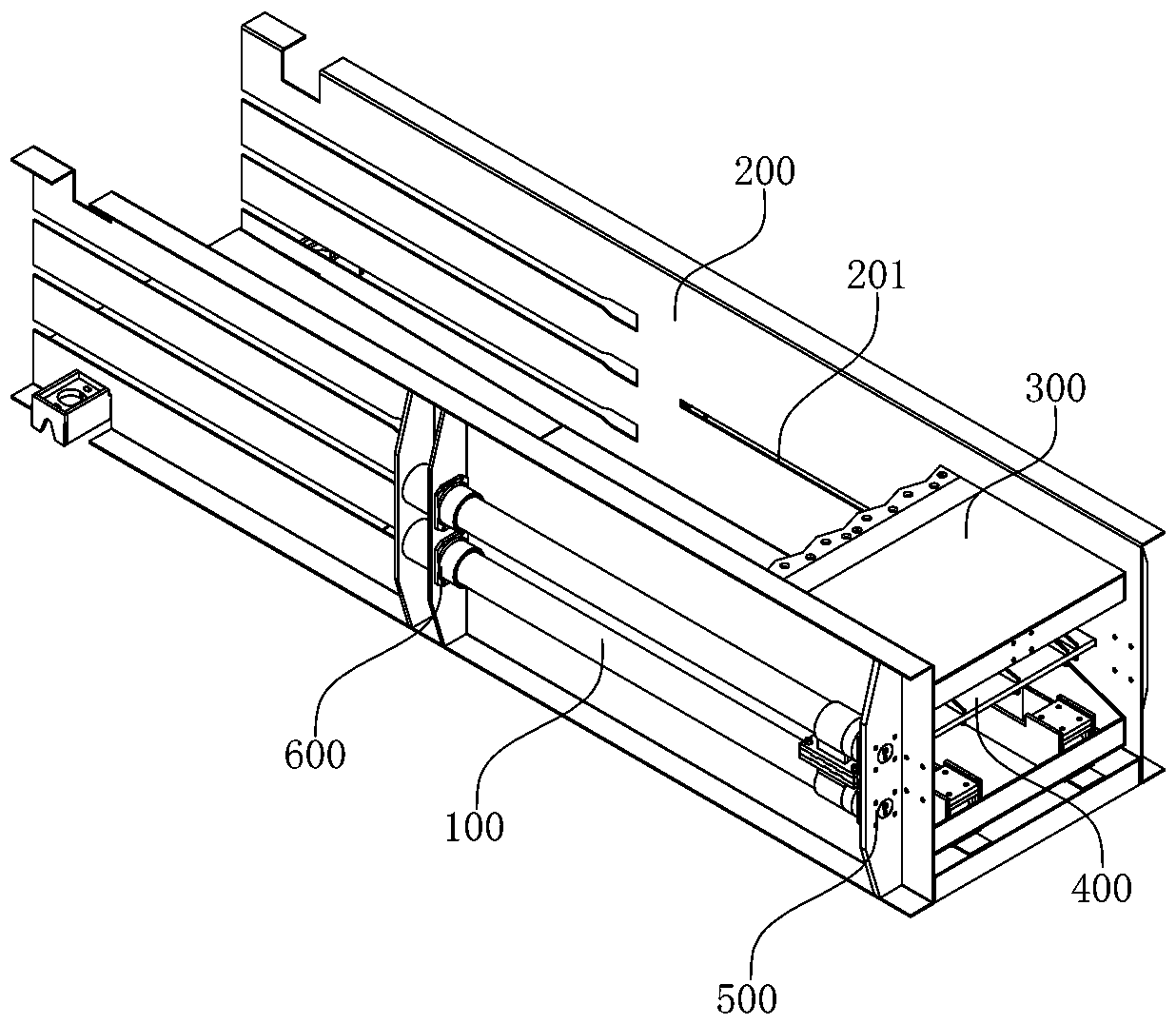
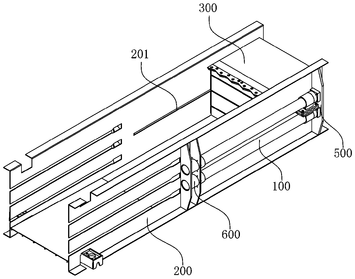
[0041] Such as Figure 2-Figure 13 , an installation structure for a push plate drive cylinder of a horizontal baler, which is arranged between the box bodies 200 on both sides and the push plate 300, including a push plate drive cylinder 100, a push plate drive plate 400, a fixing unit 500 and a guide unit 600 , multiple groups of push plate drive cylinders 100 are arranged symmetrically on both sides of the box body 200; the push plate drive plate 400 is arranged at the rear of the push plate 300; The end of 102 is fixedly arranged on the fixing unit 500 ; the guide unit 600 is arranged ...


PUM


Abstract

The invention belongs to the technical field of horizontal wrapping machines and provides an installation structure of horizontal wrapping machine push plate driving oil cylinders. Each installation structure is arranged between two side box bodies and a push plate. The installation structure comprises the multiple push plate driving oil cylinders, a push plate driving board, a fixing unit and a guide unit, wherein the multiple push plate driving oil cylinders are symmetrically arranged on the two side box bodies; the push plate driving board is arranged on the rear part of the push plate; thefixing unit is arranged on the side box bodies, and the ends of piston rods of the push plate driving oil cylinders are fixedly arranged on the fixing unit; and the guide unit is arranged on the sidebox bodies, and cylinder barrels of the push plate driving oil cylinders are slidably arranged on the guide unit. The invention further discloses a horizontal wrapping machine push plate driving device. By means of the installation structure and the driving device, the length of a wrapping machine can be decreased, therefore the wrapping machine is not limited by too much limitations of an installation site, the application range is wider, installation operation in downtown areas is more convenient, the requirements for sites are lowered, and the cost is reduced.

Description

technical field [0001] The invention belongs to the technical field of horizontal balers, and in particular relates to an installation structure of a push plate drive oil cylinder of a horizontal baler and a push plate drive device. Background technique [0002] At present, the push plate drive cylinder of the horizontal baler in the market is installed at the rear of the frame. The push position of the push plate drive cylinder is the center of the push plate. disc movement. The push plate drive cylinder body of this installation structure protrudes from the rear end face of the main frame, resulting in the overall length of the main machine being longer and requiring a larger space for installation, which increases the cost of use. The push plate drive cylinder of this type of horizontal baler is designed in a single piece. When doing work in motion, it is distributed from one stress point to the surrounding. When compressing and shearing materials, it is easy to cause un...

Claims


Application Information

Patent Timeline
Patent Type & Authority Applications(China)
IPC IPC(8): B65B65/02
CPCB65B65/02
Inventor 张国宾
Owner ZHENGZHOU XIELI CONSTR EQUIP
Learn More