
Electrolyte heating method and device

A heating method and heating device technology, applied in the chemical industry, can solve the problems of large heat loss, unstable heating temperature, slow control speed, etc., and achieve the effects of stable electrolysis temperature, effective use of heat energy, and avoiding fluid resistance or air bubbles

Pending Publication Date: 2019-08-16
上海汇平新能源有限公司
View PDF13 Cites 2 Cited by
  • Summary
  • Abstract
  • Description
  • Claims
  • Application Information

AI Technical Summary

Problems solved by technology

[0003] Most heating equipment adopts oven-type heating to increase the electrolyte temperature. Oven-type heating has the following disadvantages: the heating section is relatively small, the heating temperature is unstable after the electrolyte flow rate increases, and the control speed is slow; the oven occupies a large area and cannot Effective use of space, large heat loss, which is not conducive to energy saving in production; the oven temperature rises slowly, and the oven needs to be opened in advance before each production, and the production requirements can only be achieved after the temperature is stable; the cost is high, and frequent cleaning is required, which is not conducive to widespread use

Method used


Image

  • Electrolyte heating method and device
  • Electrolyte heating method and device

Examples


example 1

[0047] Turn on each heater in turn. Specifically, adjust the temperature to 50°C in the preheating stage, adjust the temperature to 65°C in the heating stage, adjust the temperature to 60°C in the holding stage, and adjust the temperature to 65°C in the temperature compensation stage. After the temperature is stable, turn on the electrolysis liquid transfer pump. At this time, the measured electrolyte outlet temperature was 25.3°C (that is, the electrolyte temperature when the electrolyte was output from the storage room), and the electrolyte temperature at the liquid injection port was 62.1°C. Observe that there are bubbles in the electrolyte at the liquid injection port.

example 2

[0049] Turn on each heater in turn. Specifically, adjust the temperature to 40°C in the preheating stage, adjust the temperature to 65°C in the heating stage, adjust the temperature to 60°C in the holding stage, and adjust the temperature to 65°C in the temperature compensation stage. After the temperature is stable, turn on the electrolysis liquid transfer pump. At this time, the measured electrolyte outlet temperature was 25.2°C (that is, the electrolyte temperature when the electrolyte was output from the storage room), and the electrolyte temperature at the liquid injection port was 62.4°C. It was observed that the number of bubbles in the electrolyte at the liquid injection port decreased significantly.

example 3

[0051]Turn on each heater in turn. Specifically, adjust the temperature to 35°C in the preheating stage, adjust the temperature to 60°C in the heating stage, adjust the temperature to 60°C in the holding stage, and adjust the temperature to 60°C in the temperature compensation stage. After the temperature is stable, turn on the electrolysis liquid transfer pump. At this time, the measured electrolyte outlet temperature was 25.2°C (that is, the electrolyte temperature when the electrolyte was output from the storage room), and the electrolyte temperature at the liquid injection port was 59.4°C. It was observed that the number of bubbles in the electrolyte at the liquid injection port was significantly reduced. By adjusting the difference between the overall temperature and the initial temperature, there is obviously no air bubbles at the liquid injection port.

[0052] From the above three examples, it can be seen that by adjusting the difference between the temperature in the ...


PUM


Abstract

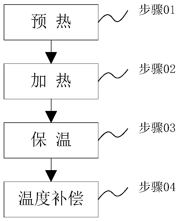
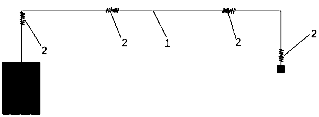
The invention relates to an electrolyte heating method and device, and belongs to the technical field of chemical engineering. The method comprises the following steps of preheating, heating, heat preserving, and temperature compensation. The electrolyte heating device comprises an electrolyte conveying pipe and multiple heaters. The liquid conveying pipe is used for conveying an electrolyte to anelectrolyte to an electrolyte injection room from an electrolyte storage room, the heaters are used for heating the multiple portions of the electrolyte conveying pipe, the portions comprise the electrolyte conveying pipe at the connecting position of the electrolyte storage room and the electrolyte injection room, a front half segment electrolyte conveying pipe of the electrolyte injection room,a rear half segment electrolyte conveying pipe of the electrolyte injection room and an electrolyte conveying pipe on an electrolyte injection machine electrolyte outlet. Through segmented heating and heat preservation, heat energy is effectively used, electrolyte temperature stability is maintained, a preheating device is started for stabilizing the electrolyte and room temperature difference, and the phenomenon that due to the large temperature difference, fluid resistance or bubbles are generated is avoided.

Description

technical field [0001] The invention relates to the technical field of chemical industry, in particular to an electrolyte heating method and device. Background technique [0002] In battery production, it is necessary to heat the electrolyte to reduce the storage time after the battery is injected and improve the wetting ability of the electrolyte. [0003] Most of the heating equipment adopts oven-type heating to increase the temperature of the electrolyte. The oven-type heating has the following disadvantages: the heating section is relatively small, and after the electrolyte flow rate increases, the heating temperature is unstable and the control speed is slow; the oven occupies a large area and cannot Effective use of space, large heat loss, which is not conducive to energy saving in production; the oven temperature rises slowly, and the oven needs to be opened in advance before each production, and the production requirements can only be met after the temperature is sta...

Claims


Application Information

Patent Timeline
Patent Type & Authority Applications(China)
IPC IPC(8): F24H1/14F24H9/18F24H9/20H01M6/00H01M10/04
CPCF24H1/14F24H9/18F24H9/20H01M6/00H01M10/04Y02P70/50
Inventor 于井锐黄全安汪丽丽姜雨松
Owner 上海汇平新能源有限公司
Learn More