Rotary self-locking SC type optical cable connector and assembly structure thereof

An optical cable connector, self-locking technology, applied in the direction of light guide, optics, instruments, etc., can solve the problems of ineffective anti-unplugging, contamination of the connector end face, accidental damage, etc., to improve the safety of use and ensure the reliability of connection. , to ensure the effect of smooth connection

Pending Publication Date: 2019-08-16
XDK COMM EQUIP HUIZHOU
View PDF0 Cites 2 Cited by
  • Summary
  • Abstract
  • Description
  • Claims
  • Application Information

AI Technical Summary

Problems solved by technology

[0003] The existing SC-type optical cable connector is connected to the adapter with a bayonet structure. In the use of the data center chassis, the SC-type optical cable connector can be easily pulled out due to the setting of the bayonet structure. cause loss
Another example is that if the optical modem has been connected for a long time or has been accidentally pulled out, the SC type optical cable connector is easy to fall off, causing the end face of the connector to be dirty. , The dirt on the end face will seriously affect the network signal. At this time, repairs need to be performed by professionals.

Method used


Image

  • Rotary self-locking SC type optical cable connector and assembly structure thereof
  • Rotary self-locking SC type optical cable connector and assembly structure thereof
  • Rotary self-locking SC type optical cable connector and assembly structure thereof

Examples


Example Embodiment

[0025] The implementation of the present invention will be described in detail below in conjunction with the accompanying drawings. The accompanying drawings are only for reference and description, and do not constitute a limitation to the protection scope of the present invention.

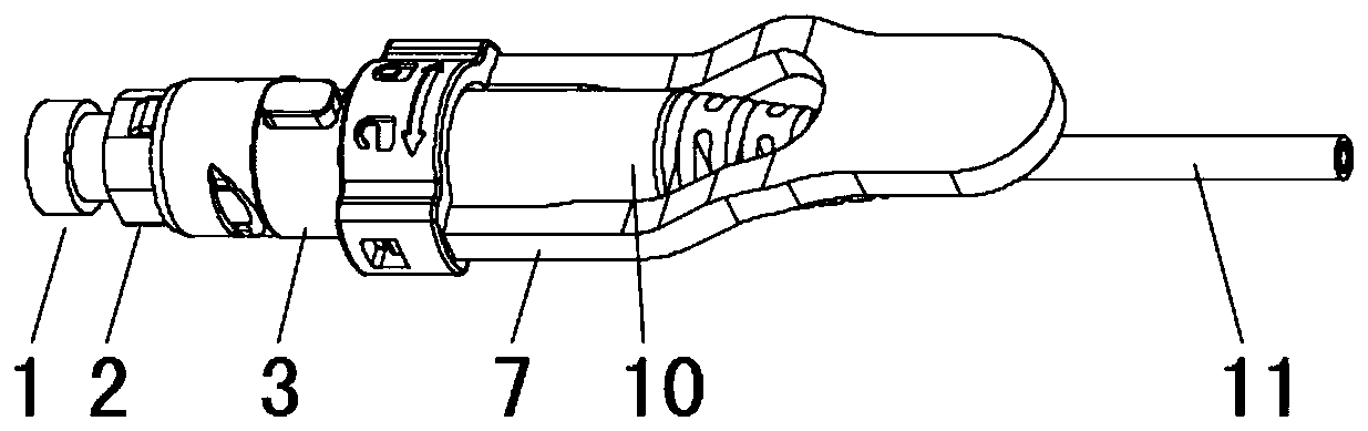
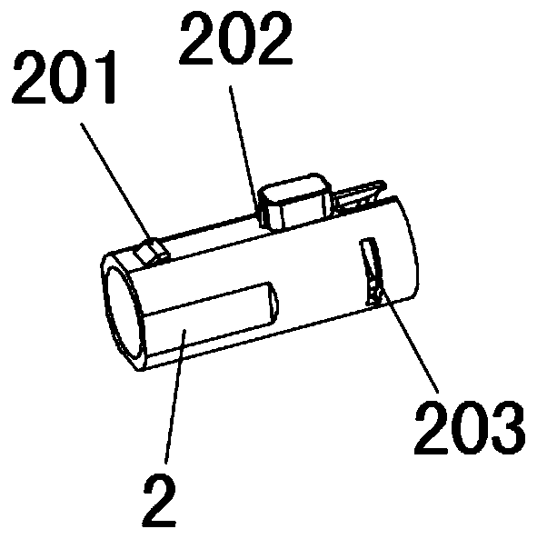
[0026] like Figure 1-2 As shown, this embodiment provides a rotary self-locking SC type optical cable connector, including an SC inner frame 2, an SC rotating outer frame 6 and a boot 10, and a belt is provided between the SC inner frame 2 and the SC rotating outer frame 6. Tail shank ferrule 3, spring 4 and stop seat 5 are provided with rotating pull rod 7, horn ring 8, and ring 9 between SC rotating outer frame 6 and tail sleeve 10, and optical cable 11 is connected from tail sleeve 10; Figure 3-4 As shown, the top of the SC inner frame 2 is provided with an inclined boss 201 and a raised column 202, and the two side walls of the rear end of the SC inner frame 2 are provided with a pair of arc...


PUM


Abstract

The invention provides a rotary self-locking SC type optical cable connector and an assembly structure thereof. A mortise provided with a tail handle as well as a spring and a locking seat are arranged between an SC inner frame and an SC rotary outer frame of the connector, a rotary pull rod, a loudspeaker ring and a circular ring are arranged between the SC rotary outer frame and a tail sleeve, and an optical cable is connected from the tail sleeve; an inclined boss and a raised column are arranged at the top of the SC inner frame, and arc-shaped holes matched with an arc-shaped fixture blockon the locking seat are formed in the two side walls of the rear end of the SC inner frame; a first groove matched with the raised column is formed in the top of the SC rotary outer frame, the frontend of the SC rotary outer frame is matched with the inclined boss, a second groove is formed in the rear end of the SC rotary outer frame, and a third groove is formed in the front end of the SC rotary outer frame; and a fixture block matched with the second groove is arranged at the front end of the rotary pull rod, and a handle is arranged at the rear end of the rotary pull rod. The rotary self-locking SC type optical cable connector provided by the invention locks an optical cable connector by virtue of a specific self-locking structure, the connector is prevented from being pulled out bymistake, connection reliability of the connector with an adapter is guaranteed, smooth network signal connection is guaranteed, and use safety of the connector is improved.

Description

technical field [0001] The invention relates to the technical field of an optical cable connector and its assembly structure, in particular to a rotary self-locking SC type optical cable connector and its assembly structure. Background technique [0002] With the rapid development of the optical communication industry, conventional optical jumpers, optical connectors and other products are widely used, especially conventional LC, SC, FC, ST and other optical cable connectors. In the application of FTTH fiber to the home, chassis, and optical modem, the demand for SC connectors has greatly increased. [0003] The existing SC-type optical cable connector is connected to the adapter with a bayonet structure. In the use of the data center chassis, the SC-type optical cable connector can be easily pulled out due to the setting of the bayonet structure. cause loss. Another example is that if the optical modem has been connected for a long time or has been accidentally pulled out...

Claims


Application Information

Patent Timeline
IPC IPC(8): G02B6/38
CPCG02B6/3821G02B6/3825G02B6/3831G02B6/3895
Inventor 张伟东曹正辉黄关庭
Owner XDK COMM EQUIP HUIZHOU
Why Eureka
Try Eureka