Synchronous reluctance motor rotor structure, motor and compressor

A technology of synchronous reluctance motor and rotor structure, which is applied in the field of compressor equipment and can solve problems such as low motor efficiency

Active Publication Date: 2019-08-16
GREE ELECTRIC APPLIANCES INC
View PDF5 Cites 6 Cited by
  • Summary
  • Abstract
  • Description
  • Claims
  • Application Information

AI Technical Summary

Problems solved by technology

[0005] The main purpose of the present invention is to provide a synchronous reluctance motor rotor structure, motor and compressor, to solve the problem of low motor efficiency in the prior art

Method used


Image

  • Synchronous reluctance motor rotor structure, motor and compressor
  • Synchronous reluctance motor rotor structure, motor and compressor
  • Synchronous reluctance motor rotor structure, motor and compressor

Examples


Embodiment Construction

[0031] It should be noted that, in the case of no conflict, the embodiments in the present application and the features in the embodiments can be combined with each other. The present invention will be described in detail below with reference to the accompanying drawings and examples.

[0032] It should be noted that the terminology used here is only for describing specific implementations, and is not intended to limit the exemplary implementations according to the present application. As used herein, unless the context clearly dictates otherwise, the singular is intended to include the plural, and it should also be understood that when the terms "comprising" and / or "comprising" are used in this specification, they mean There are features, steps, operations, means, components and / or combinations thereof.

[0033] It should be noted that the terms "first" and "second" in the specification, claims and drawings of the present application are used to distinguish similar objects, ...


PUM


Abstract

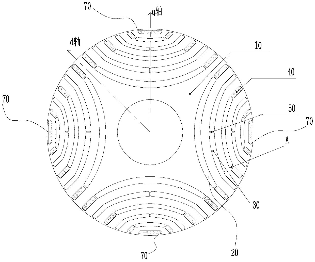
The invention provides a synchronous reluctance motor rotor structure, a motor and a compressor. The synchronous reluctance motor rotor structure comprises a rotor core, first type slit grooves and second type slit grooves are set in the rotor core, the first type slit grooves and the second type slit grooves are alternately arranged in the q axis direction of the rotor core, wherein two ends of each of the first type slit grooves are provided with two filling slit grooves, and the second type slit grooves are air grooves. By setting the first type slit grooves and the second slit grooves, setting the filling slit grooves at two ends of the first type slit grooves and setting the second type slit grooves to be the air grooves, the efficiency of the motor with the rotor structure can be effectively improved, at the same time, the rotor structure can avoid the severe deformation during manufacturing, the amount of materials used for manufacturing the rotor structure can be reduced, and therefore, the production cost of the motor is effectively reduced.

Description

technical field [0001] The invention relates to the technical field of compressor equipment, in particular to a synchronous reluctance motor rotor structure, a motor and a compressor. Background technique [0002] The asynchronous start synchronous reluctance motor combines the structural characteristics of the induction motor and the synchronous reluctance motor. The torque is generated by the squirrel cage induction to realize the start, and the multi-layer reluctance groove is set on the rotor to generate the reluctance torque to realize the constant speed operation. Turn on the power to start the operation. Compared with the permanent magnet motor, the asynchronous start synchronous reluctance motor has no rare earth permanent magnet material, and there is no problem of demagnetization. The motor has low cost and good reliability. Moreover, many air magnetic barriers are arranged on the rotor of the motor, so that the cooling effect is good and the loss of the rotor is ...

Claims


Application Information

Patent Timeline
Patent Type & Authority Applications(China)
IPC IPC(8): H02K1/22H02K1/32H02K1/26H02K15/02
CPCH02K1/22H02K1/265H02K1/32H02K15/0012H02K15/02
Inventor 胡余生陈彬史进飞肖勇李霞余钦宏
Owner GREE ELECTRIC APPLIANCES INC
Why Eureka
Try Eureka