

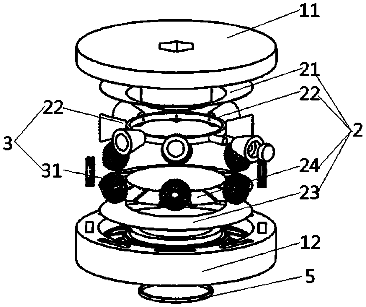
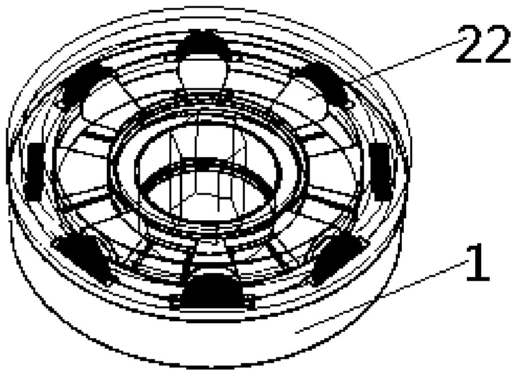
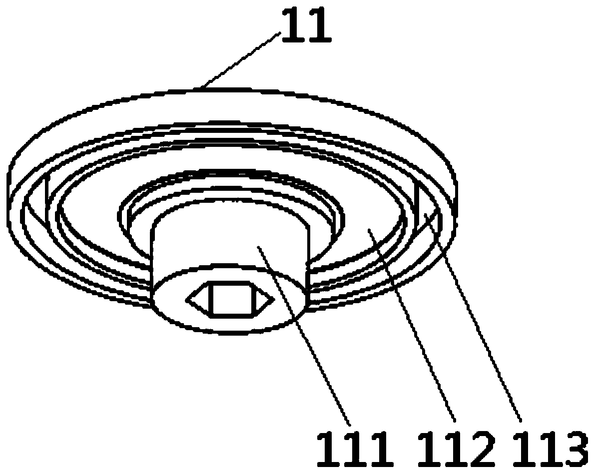
Environment mechanical energy composite collection and conversion device
A conversion device and mechanical energy technology, which is applied in the field of environmental mechanical energy composite collection and conversion devices, can solve the problems of inability to meet the power supply requirements of low-power portable devices and sensor nodes, low power output efficiency, and poor compatibility
- Summary
- Abstract
- Description
- Claims
- Application Information
AI Technical Summary
Problems solved by technology
Method used
Image

Examples
Embodiment Construction
[0033] The following will clearly and completely describe the technical solutions in the embodiments of the present invention with reference to the accompanying drawings in the embodiments of the present invention. Obviously, the described embodiments are only some, not all, embodiments of the present invention. Based on the embodiments of the present invention, all other embodiments obtained by persons of ordinary skill in the art without making creative efforts belong to the protection scope of the present invention.
[0034] The core of the present invention is to provide an environmental mechanical energy compound collection and conversion device, which can refit and replace the collection device according to the characteristics of different environments, so as to increase the application range of the entire energy collection device, and adopts electromagnetic and frictional composite power generation design, While capturing a large amount of kinetic energy, it can be effic...
PUM
 Abstract
Description
Claims
Application Information