
Lora signal monitoring system and method for multi-node software radio platform

A software radio and signal monitoring technology, applied in the field of communication, can solve the problems of low processing speed, large influence of detection probability deployment location, and inability to detect LoRa signals, etc., to reduce errors, improve detection probability, and overcome low detection probability Effect

Active Publication Date: 2020-08-25
XIDIAN UNIV
View PDF7 Cites 0 Cited by
  • Summary
  • Abstract
  • Description
  • Claims
  • Application Information

AI Technical Summary

Problems solved by technology

The shortcomings of this test system are: the test system uses MCU (micro control unit) to drive the Lora module for testing, and the processing speed of MCU (micro control unit) is not high, resulting in the inability to quickly detect the Lora signal
The disadvantage of this method is: since this method uses the method of detecting known frequency points to detect LoRa signals, parameter information such as frequency must be configured when performing LoRa signal testing, resulting in this method can only detect known frequency point information Whether there is a LoRa signal on a single fixed frequency point, it is impossible to detect a LoRa signal with unknown frequency point information in a certain frequency band
The steps of the method are to use Field-Programmable Gate Array FPGA (Field-Programmable Gate Array) to carry out data communication and logical control of multiple Lora modules, to realize the function of parallel data acquisition and transmission, after the data is aggregated into the FPGA, the FPGA then The parallel data is sent to the microcontroller through the high-speed serial interface for processing. After the microcontroller receives the data, it analyzes the data and judges the information of a certain channel. The disadvantage of this method is: because this method uses multiple LoRa modules For channel detection, this method can only detect whether there are LoRa signals on multiple fixed-frequency points with known multi-frequency point information, and cannot detect LoRa signals with unknown frequency point information, and the detection probability is greatly affected by the deployment position of the monitoring device , the probability of LoRa signal detection is low

Method used


Image

  • Lora signal monitoring system and method for multi-node software radio platform
  • Lora signal monitoring system and method for multi-node software radio platform

Examples


Embodiment Construction

[0049] The present invention will be further described below in conjunction with the accompanying drawings.

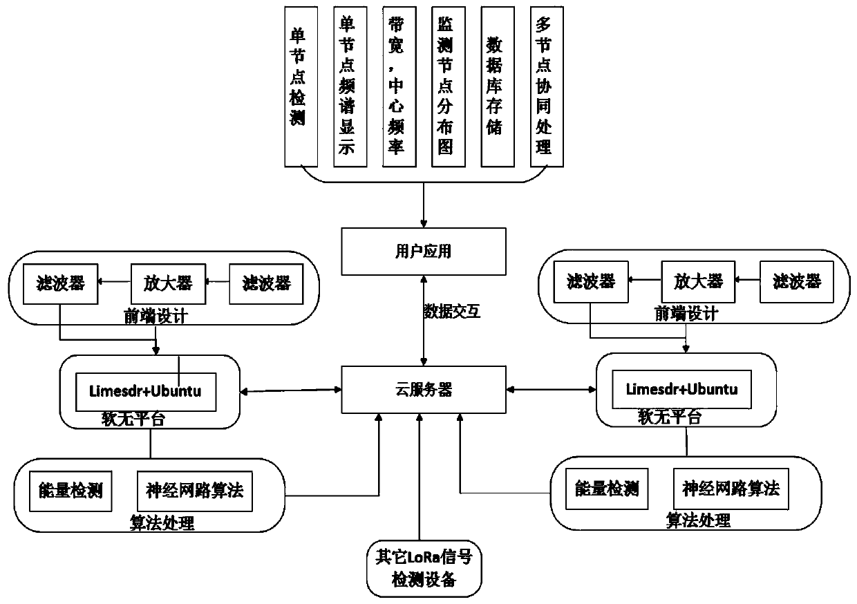
[0050] Refer to attached figure 1 , to further describe the Lora signal monitoring system of the present invention.

[0051] The Lora signal monitoring system of the present invention includes two parts: Lora signal monitoring and a data fusion center.

[0052] The Lora signal monitoring part includes multiple Lora signal monitoring nodes. The Lora signal monitoring node includes a radio frequency front-end processing module, a software radio platform hardware processing module, a signal data processing module, and a monitoring node host computer software module. The RF front-end processing module includes an antenna module, a primary low-pass filter module, an amplifier module, and a secondary low-pass filter module. The signal data processing module includes an energy detection module and a convolutional neural network modulation recognition module.

[0053] The ...


PUM


Abstract

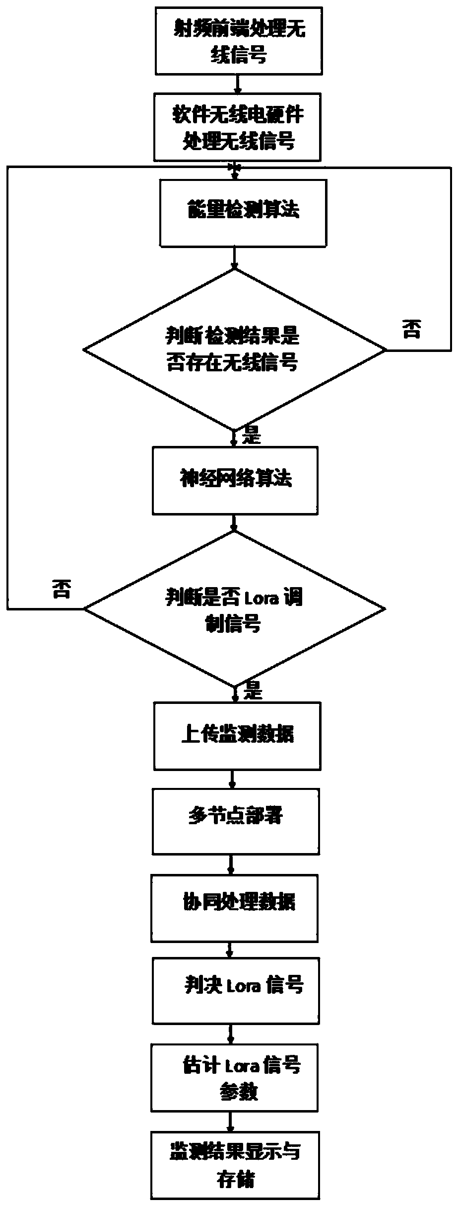
A multi -node software radio platform LoRa signal monitoring system and method, including LORA signal monitoring and data fusion center; LORA signal monitoring parts include multiple LORA signal monitoring nodes; LORA signal monitoring nodes include radio frequency front -end processing modules, software radio electricityThe platform hardware processing module, signal data processing module, and monitoring node upper machine software module; the data fusion center includes cloud server modules and user application software modules.The present invention uses RF front end to pre -process the wireless signal, uses energy detection and convolutional neural network modulation identification algorithm to identify the LORA signal, and deploy multi -node monitoring.Estimation of parameters.The invention can identify and estimate the LoRa signal of unknown frequency information, which increases the probability of LORA signal detection.

Description

technical field [0001] The present invention relates to the technical field of communication, and further relates to a monitoring system and method for a long-distance wide-area Lora (Long-Range) signal based on a multi-node software radio platform in the technical field of wireless communication. Under the condition of ensuring the detection performance, the present invention detects and identifies the Lora signal on the software radio platform, and estimates the parameter information such as the center frequency and bandwidth of the signal, and implements multi-node cooperative detection to improve the detection probability, thereby completing the monitoring of the Lora signal . Background technique [0002] Lora is an emerging communication technology for the Internet of Things. It is widely used in factories, factories, mines, farms and other places because of its long transmission distance and low power consumption. With the continuous expansion of its application field...

Claims


Application Information

Patent Timeline
Patent Type & Authority Patents(China)
IPC IPC(8): H04B17/309H04B17/318H04L29/08G06K9/62
CPCH04B17/309H04B17/318H04L67/10G06F18/23211
Inventor 易运晖赵海浪李力
Owner XIDIAN UNIV
Learn More