Rotary small-size paint spraying chamber convenient to move

A spray booth and rotary technology, applied in the spray booth, spraying device, etc., can solve the problems of large volume of spray booth, inconvenient movement, uneven spraying, etc., achieve uniform spraying, prevent precipitation, and solve the effect of uneven spraying

Inactive Publication Date: 2019-08-20
马单智
View PDF5 Cites 24 Cited by
  • Summary
  • Abstract
  • Description
  • Claims
  • Application Information

AI Technical Summary

Problems solved by technology

[0003] The existing spray booth is large in size, inconvenient to move, and the spray paint is not uniform enough

Method used


Image

  • Rotary small-size paint spraying chamber convenient to move
  • Rotary small-size paint spraying chamber convenient to move
  • Rotary small-size paint spraying chamber convenient to move

Examples


Embodiment 1

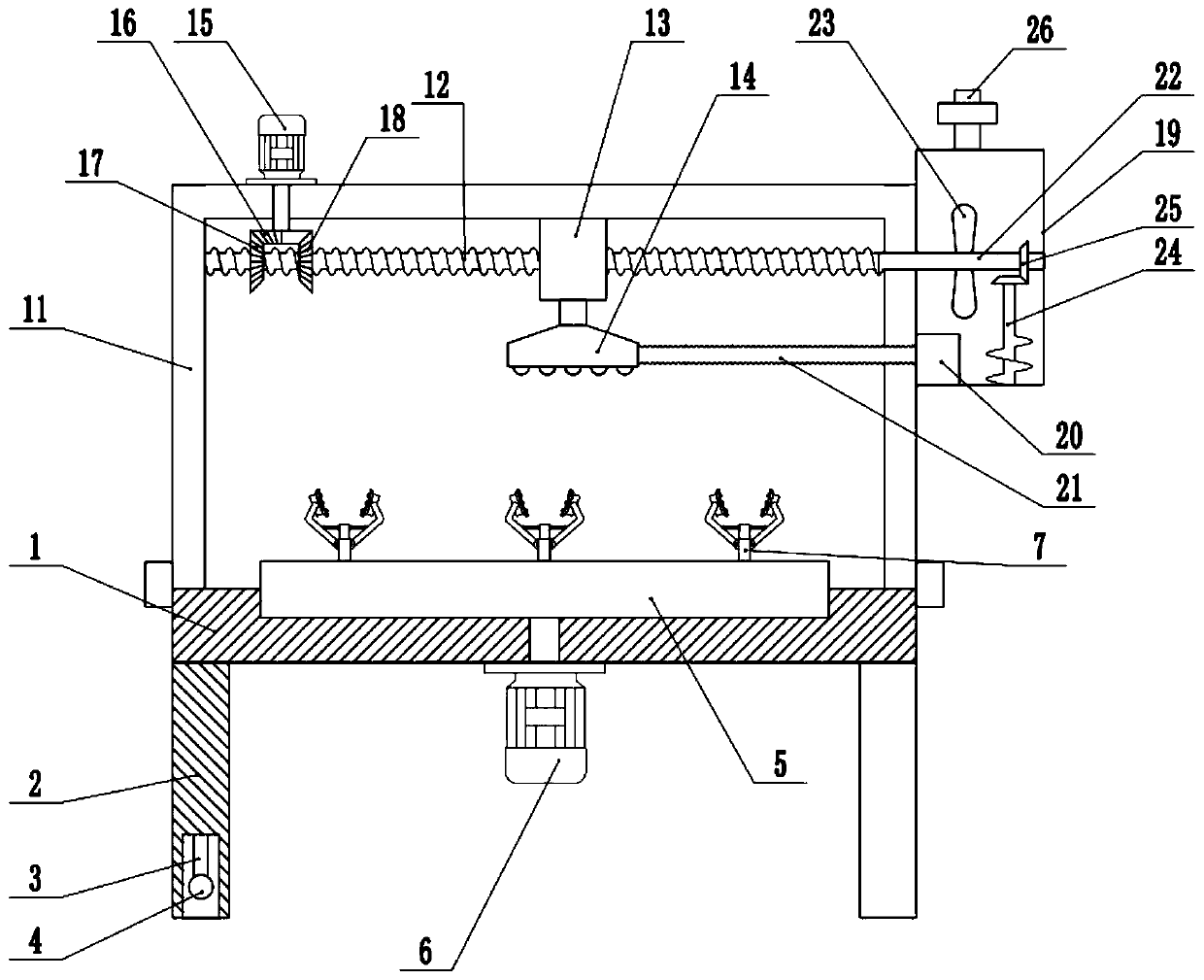
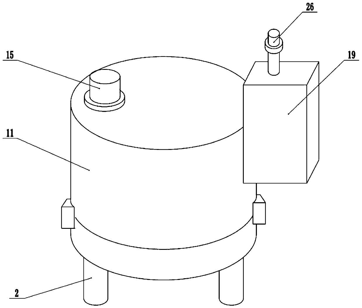
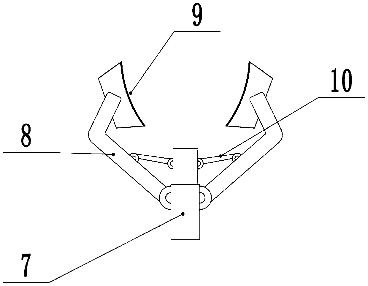
[0020] see Figure 1-3 , in the embodiment of the present invention, a kind of rotary small-sized spray booth that is convenient to move comprises workbench 1, nozzle 14, material storage box 19 and paint pump 20, and the upper surface of workbench 1 is connected with turntable 5 in rotation, and workbench 1 Rotary motor 6 is fixedly connected to the bottom of the rotary motor 6, and the shaft end of the rotary motor 6 passes through the workbench 1 to connect with the turntable 5. The rotary motor 6 can drive the turntable 5 to rotate. There are several clamping mechanisms distributed on the upper surface of the turntable 5. The holding mechanism includes a telescopic mechanism 7, jaws 8, a clamping plate 9 and a connecting rod 10. The lower end of the telescopic mechanism 7 is fixedly connected to the upper surface of the turntable 5, and both sides of the telescopic mechanism 7 are hinged with jaws 8. A clamping plate 9 is installed on the upper end of the jaw 8, and a conn...

Embodiment 2

[0024] On the basis of Embodiment 1, a stirring mechanism is installed in the inside of the material storage box 19, and the stirring mechanism includes a rotating shaft 22, a stirring blade 23, a screw rod 24 and a bevel gear set 25, and one end of the rotating shaft 22 is connected with the screw mandrel 12, and the rotating shaft 22 The other end of the other end is rotationally connected with the side wall of the material storage box 19, and the rotating shaft 22 is fixedly connected with the stirring blade 23. When the screw mandrel 12 rotates, the stirring blade 23 is driven to rotate, and the stirring blade 23 is used to stir the paint to prevent the paint from depositing. The bottom of 19 is rotatably connected with screw rod 24, and the upper end of screw rod 24 is connected with rotating shaft 22 through bevel gear set 25. When rotating shaft 22 rotates, it drives screw rod 24 to rotate, and utilizes screw rod 24 to stir the bottom paint, further preventing the paint f...


PUM


Abstract

The invention relates to the field of machining equipment, in particular to a rotary small-size paint spraying chamber convenient to move. The rotary small-size paint spraying chamber comprises a workbench, a spray head, a storage box and a paint pump; the upper surface of the workbench is rotationally connected with a rotary disc; a plurality of clamping mechanisms are distributed on the upper surface of the rotary disc; a shell is detachably installed on the upper surface of the workbench, a screw rod is arranged in the shell, and the middle of the screw rod is sleeved with a slide block; areciprocating motor is fixedly connected to the upper surface of the shell, and the spray head is fixedly connected to the lower surface of the slide block; the outer side wall of the workbench is fixedly connected with the storage box, paint is poured into the storage box through an injection pipe, and the storage box is internally provided with the paint pump and a stirring mechanism; a to-be-machined workpiece is clamped through a clamping mechanism, the clamping speed is high, and the working efficiency is improved; and in the paint spraying process, the spray head does reciprocating motion, meanwhile, the to-be-machined workpiece is driven to rotate through the rotary disc, the paint is sprayed more uniformly, and the paint is stirred by stirring blades and prevented from settling.

Description

technical field [0001] The invention relates to the field of processing equipment, more specifically, a small rotary paint spray booth that is easy to move. Background technique [0002] The spray booth is one of the painting rooms. The so-called painting room refers to the room equipped with painting machines and tools for painting operations. The spray booth is a device that provides a special environment for painting operations. The artificial environment created in the spray booth can meet the requirements of the painting operation on the temperature, humidity, illumination, and cleanliness of the environment. The painting room also includes a powder spraying room, a paint dipping room, a curtain coating room, etc. The spray booth is the most complex structure and equipment for spraying liquid paint, and it is the key equipment necessary for the painting workshop. Combining with various spraying methods (such as air spraying, airless high-pressure spraying, electrostat...

Claims


Application Information

Patent Timeline
Patent Type & Authority Applications(China)
IPC IPC(8): B05B13/02B05B13/04B05B15/25B05B16/00
CPCB05B13/0228B05B13/025B05B13/041B05B15/25B05B16/00
Inventor 马单智
Owner 马单智
Why Eureka
Try Eureka