
Nozzle shell selective laser melting forming method

A technology of laser selective melting and nozzle shell, applied in the field of additive manufacturing, can solve the problem of metal powder cannot be removed, and achieve the effect of reducing the number of parts, increasing the cleaning efficiency, and increasing the air pressure

Active Publication Date: 2019-08-20
AECC AVIATION POWER CO LTD
View PDF6 Cites 9 Cited by
  • Summary
  • Abstract
  • Description
  • Claims
  • Application Information

AI Technical Summary

Problems solved by technology

[0004] The purpose of the present invention is to overcome the above-mentioned shortcomings of the prior art, provide a laser selective melting forming method for the nozzle shell, and solve the problem that the metal powder in the closed heat insulation cavity of the nozzle shell cannot be removed

Method used


Image

  • Nozzle shell selective laser melting forming method
  • Nozzle shell selective laser melting forming method
  • Nozzle shell selective laser melting forming method

Examples


Embodiment Construction

[0030] The present invention is described in further detail below in conjunction with accompanying drawing:

[0031] The method of the present invention comprises the following steps:

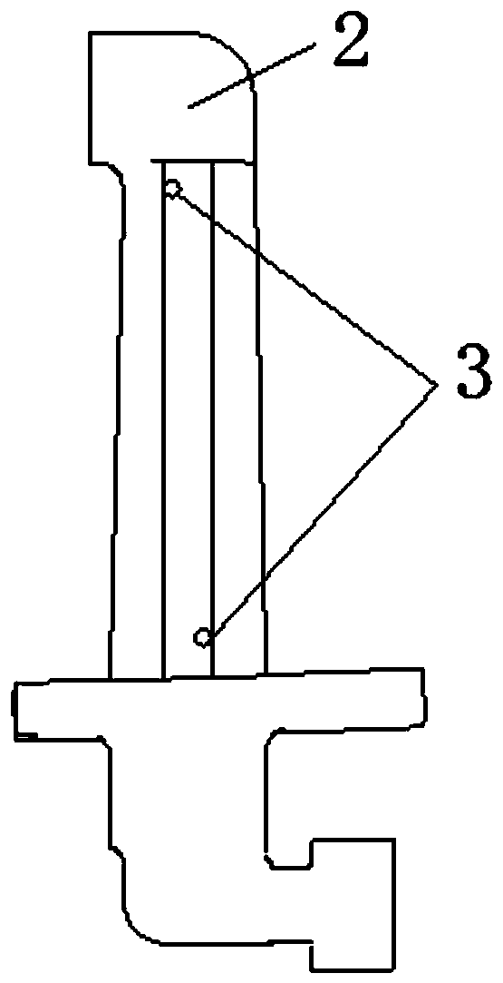
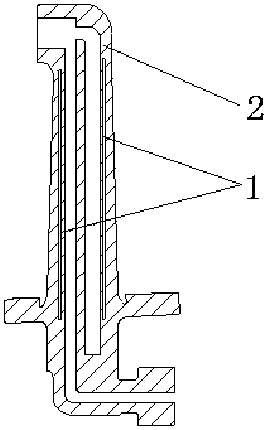
[0032] Step 1, the aviation fuel nozzle housing 2 with a closed cavity structure is formed by laser selective melting and additive manufacturing, such as Figure 1-2 As shown, the forming direction of the nozzle housing 2 parts is placed vertically.

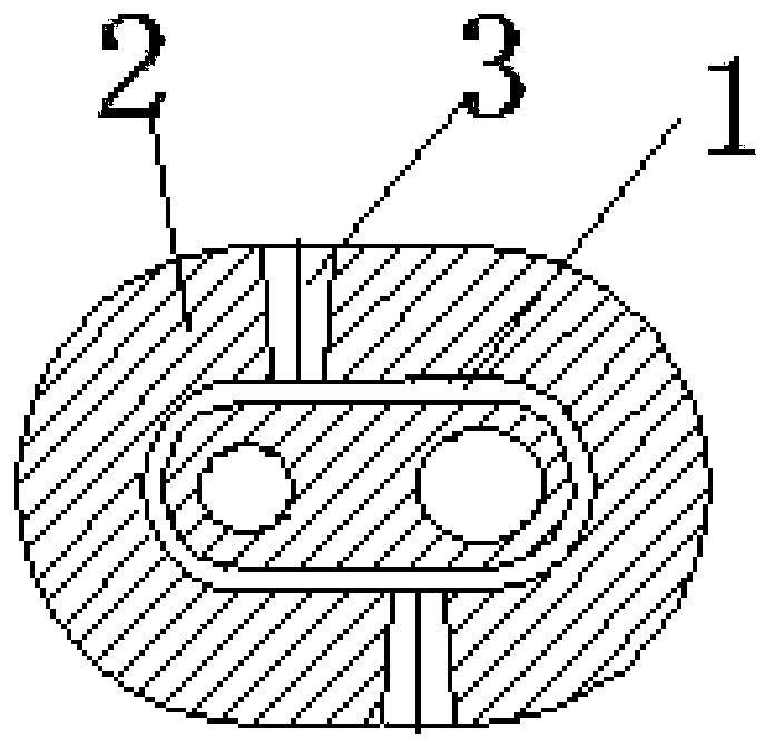
[0033] The nozzle housing 2 includes a nozzle head, a rod and a mounting plate connected in sequence. The bottom of the mounting plate is respectively provided with an oil inlet port of the main oil circuit and an oil inlet port of the auxiliary oil circuit. They are perpendicular to each other and are respectively connected to two independent oil passages. The two independent oil passages are arranged inside the rod. The nozzle head is provided with a nozzle opening. The two independent oil passages converge to the nozzle opening. A completely c...


PUM

PropertyMeasurementUnit
Diameteraaaaaaaaaa

Abstract

The invention discloses a nozzle shell selective laser melting forming method. The nozzle shell selective laser melting forming method comprises the following steps that 1, a nozzle shell and test bars are formed on a substrate through additive manufacturing, a heat insulation cavity zone of the nozzle shell is provided with at least two through holes, and the test bars and the through holes are the same in diameter and length; 2, metal powder on the surface of the substrate, the surface of the nozzle shell and the test bars is removed, and metal powder in the heat insulation cavity is removedthrough the through holes; and 3, the test bars are inserted into the through holes for sealing. The problem that metal powder in a sealed heat insulation cavity of a nozzle shell cannot be removed is solved.

Description

technical field [0001] The invention belongs to the field of additive manufacturing, and relates to a laser selective melting forming method for a nozzle shell. Background technique [0002] As an important part of an aero-engine, the fuel nozzle housing is usually formed by traditional processing techniques such as casting / forging / stamping to form multiple parts, which are combined into nozzle housing parts by assembly / welding methods. The heat insulation cavity structure of the parts is through the parts The assembly gap is realized, and problems such as deformation are prone to occur during the welding process. [0003] Additive manufacturing technology is a new type of rapid prototyping technology that intersects computers, materials, and high-energy beams. It is suitable for the rapid development of new products with complex structures and inner cavity structures. With the rapid development and technical advantages of additive manufacturing technology , the design free...

Claims


Application Information

Patent Timeline
IPC IPC(8): B22F3/105B22F3/24B22F5/10B33Y10/00
CPCB22F3/24B22F5/10B33Y10/00B22F2003/247B22F2998/10B22F10/00B22F10/66B22F10/28B22F12/38B22F12/53Y02P10/25
Inventor 吴晓锋陈娟娟谢国印李金声周亚娜刘志军王颖种磊
Owner AECC AVIATION POWER CO LTD
Features
  • Generate Ideas
  • Intellectual Property
  • Life Sciences
  • Materials
  • Tech Scout
  • Unparalleled Data Quality
  • Higher Quality Content
  • 60% Fewer Hallucinations
Learn More