Stainless steel pipe holing device

A drilling equipment, stainless steel technology, applied in the direction of drilling / drilling equipment, metal processing equipment, boring / drilling, etc., can solve the problems of large debris, laborious collection, working environment pollution, etc.

Inactive Publication Date: 2019-08-20
安徽管益生新材料科技有限公司
View PDF10 Cites 2 Cited by
  • Summary
  • Abstract
  • Description
  • Claims
  • Application Information

AI Technical Summary

Problems solved by technology

[0003] The application number is 201821632034.2, and the patent name is a technical scheme of a stainless steel tube continuous drilling device, which effectively makes up for the defects of inconvenient stainless steel tube fixing and low drilling efficiency in the existing stainless steel tube continuous drilling device
However, this technical solution uses a motor to drive a drill to drill holes in the steel pipe, which will generate a large amount of debris, pollute the working environment, and require laborious collection.

Method used


Image

  • Stainless steel pipe holing device
  • Stainless steel pipe holing device
  • Stainless steel pipe holing device

Examples


Embodiment 1

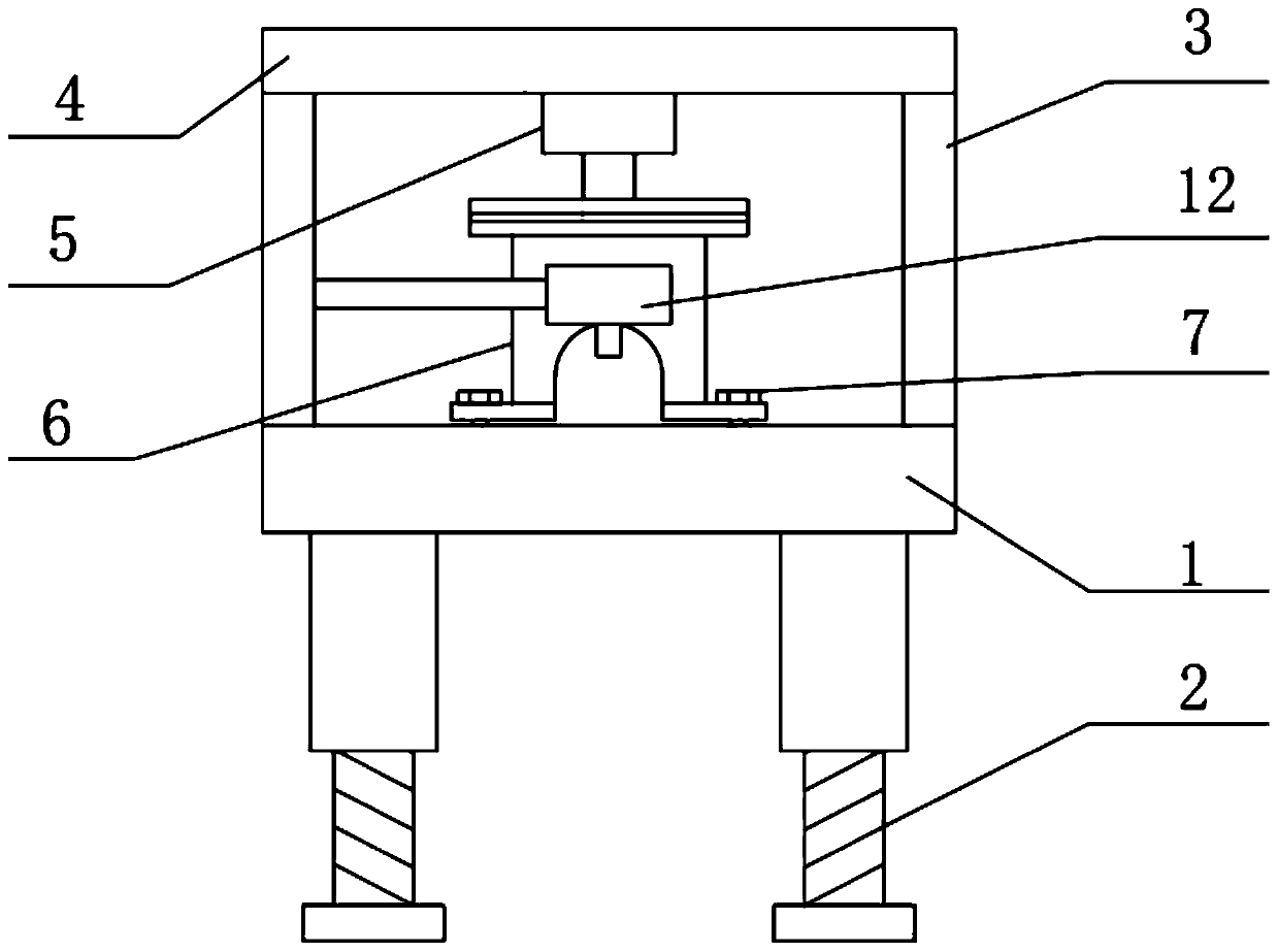
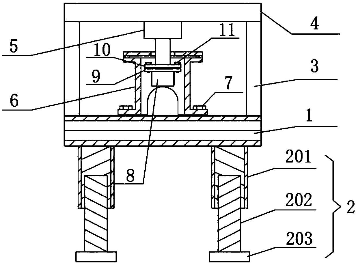
[0026] like Figure 1-6 As shown, a stainless steel pipe fitting drilling equipment includes a support body 1, the lower end of the support body 1 is connected with a support leg 2, the upper end of the support body 1 is connected with the same top plate 4 through two side plates 3, and the lower end surface of the top plate 4 A hydraulic telescopic rod 5 is connected, and a steel pipe limiting device 6 is arranged directly below the hydraulic telescopic rod 5, and the steel pipe limiting device 6 is located between the two side plates 3;

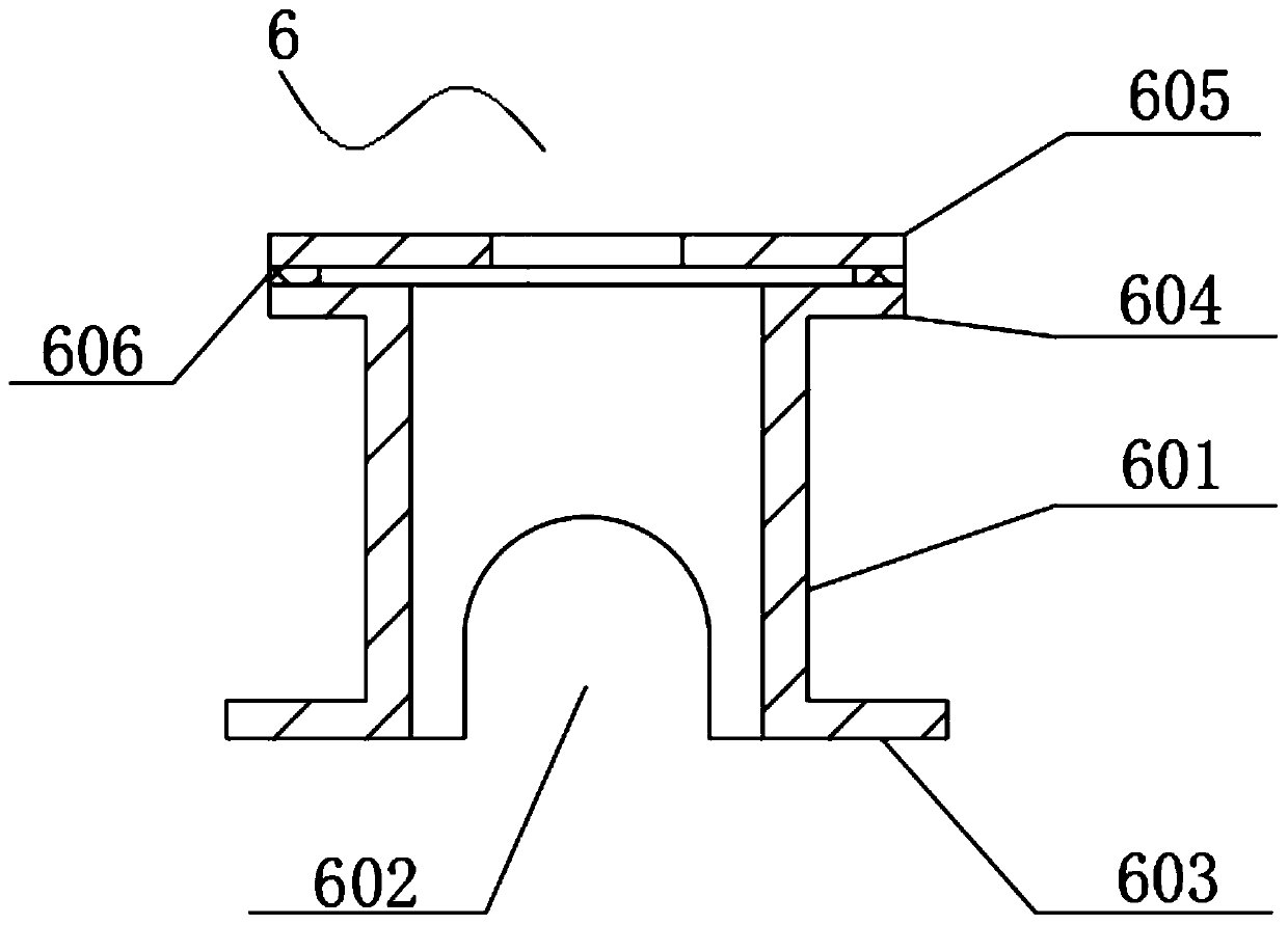
[0027] The steel pipe limiting device 6 includes a limiting sleeve 601, the lower end of the limiting sleeve 601 is provided with a limiting hole 602, and the lower end of the limiting sleeve 601 is provided with a lower flange 603, which is movable in the through hole provided on the lower flange 603. The first locking screw 7 is plugged in, and the first locking screw 7 is threadedly connected with the threaded hole provided on the upper ...


PUM


Abstract

The invention relates to the technical field of pipe holing, in particular to a stainless steel pipe holing device which comprises a supporting body. The lower end of the supporting body is connectedwith supporting legs. The upper end of the supporting body is connected with one top plate through two side plates. The lower end face of the top plate is connected with a hydraulic telescopic rod. Asteel pipe limiting device is arranged right under the hydraulic telescopic rod and is located between the two side plates. By means of the detachable connection mode between an annular blade and thehydraulic telescopic rod, the annular blade can be replaced conveniently, holes of different diameters can be drilled in a steel pipe, the annular blade is sleeved with the steel pipe limiting device,the steel pipe limiting device is fixed to the supporting body through first locking screws, the steel pipe to be holed is inserted into a limiting hole, the hydraulic telescopic rod is started to drive the annular blade to move downwards, the steel pipe is cut and holed by pressing the annular blade downwards, steel pieces which are formed in the holing process can fall in pieces, a large amountof scraps are avoided, and the tidying time is saved.

Description

technical field [0001] The invention relates to the technical field of punching pipe fittings, in particular to a punching equipment for stainless steel pipe fittings. Background technique [0002] A steel pipe is a steel material with a hollow cross-section whose length is much greater than its diameter or circumference. It can be used to transport fluids and powdered solids, exchange heat, and manufacture mechanical parts and containers. When the steel pipe is installed and used, it is necessary to punch the steel pipe. [0003] The application number is 201821632034.2, and the patent name is a technical solution for a stainless steel tube continuous drilling device, which effectively makes up for the defects of inconvenient stainless steel tube fixing and low drilling efficiency existing in the existing stainless steel tube continuous drilling device. But this technical scheme utilizes motor to drive drill bit to punch steel pipe, can produce a large amount of debris, po...

Claims


Application Information

Patent Timeline
Patent Type & Authority Applications(China)
IPC IPC(8): B23B41/00B23Q3/08B23Q3/155B23Q11/00
CPCB23B41/00B23Q3/08B23Q3/155B23Q11/0053
Inventor 朱向勇
Owner 安徽管益生新材料科技有限公司
Why Eureka
Try Eureka