Telescopic multifunctional bus gripper and working method thereof

A bus, multi-functional technology, applied in the direction of vehicle components, special location of the vehicle, transportation and packaging, etc., can solve the problems of bus supporting facilities that cannot travel, mobile phones cannot be charged in time, passenger communication barriers, etc., to achieve close cooperation Strong, uniform force, not easy to fall off

Inactive Publication Date: 2019-08-20
SHANDONG UNIV OF SCI & TECH
View PDF8 Cites 4 Cited by
  • Summary
  • Abstract
  • Description
  • Claims
  • Application Information

AI Technical Summary

Problems solved by technology

[0003] The bus is crowded with people and the noise is loud, especially for some passengers who are not familiar with the route, so that the passengers cannot hear the station announcement or cannot press the stop bell in time after hearing the station announcement and miss the next stop, which brings great inconvenience to the travel of passengers. great inconvenience
[0004] Mobile phones have become an indispensable item for mod

Method used


Image

  • Telescopic multifunctional bus gripper and working method thereof
  • Telescopic multifunctional bus gripper and working method thereof
  • Telescopic multifunctional bus gripper and working method thereof

Examples


Example Embodiment

[0044] Example 1:

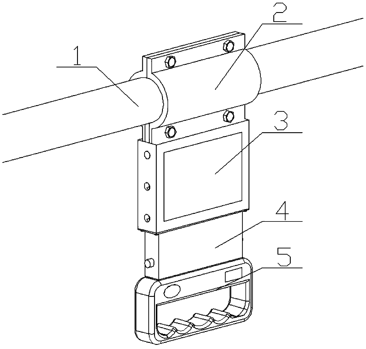
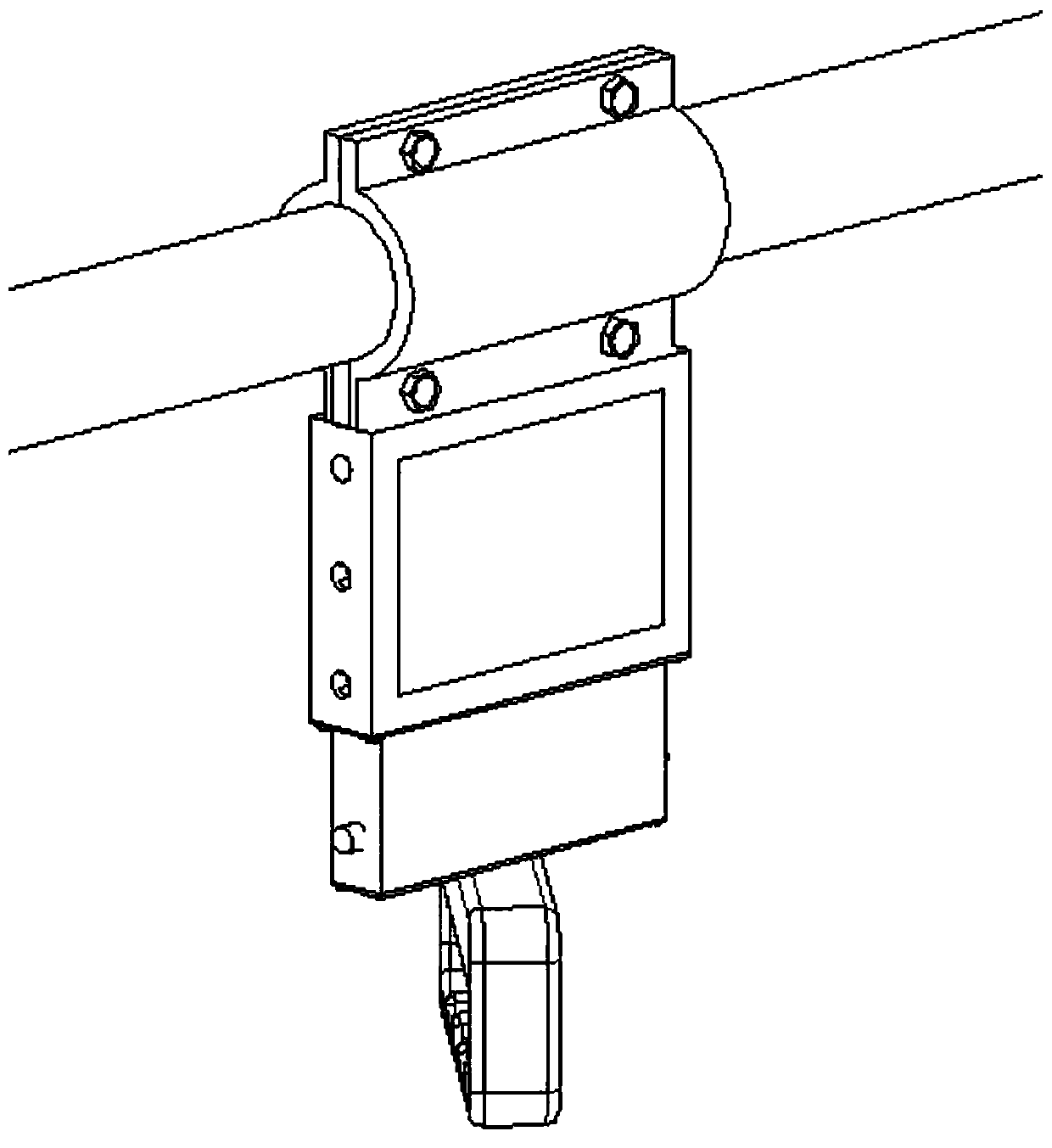
[0045] A retractable multifunctional bus gripper includes a support rod, a fixed clamp is sleeved on the support rod, and a pull rod is provided on the lower side of the fixed clamp. The pull rod includes a vertically arranged upper rod and a lower rod, The upper rod and the lower rod are slidingly connected, and the lower side of the rod is provided with a gripper. Through the relative sliding between the upper rod and the lower rod, height adjustment is realized to adapt to passengers of different heights.

[0046] The upper pull rod is a hollow rectangular body, the inner walls of the upper pull rod are provided with grooves on the two side walls, and the two sides are symmetrically provided with limit holes. The number of first limiting holes on each side surface is three. It can be pulled to different limit holes and adjusted to different lengths according to actual needs.

[0047] The pull-down rod is arranged in the hollow cavity of the upper pull rod. T...

Example Embodiment

[0048] Example 2:

[0049] A retractable multifunctional bus gripper, the structure of which is as described in Example 1, the difference is that: the bottom of the groove of the upper rod is provided with a slider baffle to prevent the lower rod and the upper rod from being disjointed. When the guide slider slides to the slider baffle at the lower end of the upper pull rod, the cylindrical limit piece and the second limit hole are just combined, such as Figure 8 Shown.

Example Embodiment

[0050] Example 3:

[0051] A retractable multifunctional bus gripper, the structure of which is as described in embodiment 1, the difference is: the fixed clamping band includes two semi-arc clamping plates, and the clamping plates are provided to be compatible with the support rod The two clamping pieces are clamped on the support rod, and the clamping pieces are connected by bolts; it is convenient to disassemble and install, and the fixing is firm.


PUM


Abstract

The invention relates to a telescopic multifunctional bus gripper and a working method thereof, and belongs to the technical field of vehicle accessories; the device comprises a fixing tightening hooparranged on a supporting rod in a sleeving mode; a pull rod is arranged on the lower side of the fixing tightening hoop and comprises an upper pull rod and a lower pull rod which are vertically arranged; the upper pull rod and the lower pull rod are in sliding connection to achieve height adjustment so as to adapt to passengers with different heights, and a gripper is arranged on the lower side of the pull rod. The lower pull rod slides in a groove of the upper pull rod through a guide sliding block; the relative positions of the lower pull rod and the upper pull rod are adjusted through a control rod in the lower pull rod; height adjustment is achieved; the process is simple, connection is firm, falling of the gripper is not likely to happen in a vehicle shaking process, and safety and stability effects are achieved.

Description

technical field [0001] The invention relates to the technical field of vehicle accessories, in particular to a retractable multifunctional bus gripper and a working method thereof. Background technique [0002] At present, urban traffic is becoming more and more congested, and buses have become the main means of transportation for people to travel in cities. Due to the large number of passengers and the limited number of bus seats, many passengers need to stand on the bus. Because the height of the passengers is different and the height of the grip is fixed, it is very inconvenient for the shorter passengers to grab the grip. There will inevitably be bumps when the car is running, and its body balance needs to be maintained by the handle. It is necessary for every standing passenger to be able to grasp the handle. [0003] The bus is crowded with people and the noise is loud, especially for some passengers who are not familiar with the route, so that the passengers cannot h...

Claims


Application Information

Patent Timeline
IPC IPC(8): B60N3/02
CPCB60N3/02B60N3/026
Inventor 于涛缑延强邓增阁刘洋闫家奇李玉增
Owner SHANDONG UNIV OF SCI & TECH
Why Eureka
Try Eureka