Airport runway crack detection and maintenance equipment

A technology for airport runways and maintenance equipment, applied in road repair, roads, roads, etc., can solve problems such as performance degradation, damage to pavement structure, and difficulty in viewing crack depth, and achieve a good crack repair effect.

Active Publication Date: 2019-08-20
ZHENGZHOU UNIVERSITY OF AERONAUTICS
View PDF5 Cites 2 Cited by
  • Summary
  • Abstract
  • Description
  • Claims
  • Application Information

AI Technical Summary

Problems solved by technology

[0002] In recent years, China's civil aviation industry has developed rapidly, and the total turnover of air transport has ranked second in the world. However, with the rapid growth of air traffic volume and the proportion of large-scale wide-body technology, some early-built airport runways may be in places with large temperature differences. The airport runway built in the area has serious damage to the pavement structure. It is more common that there are many cracks on the runway pavement, and these cracks are usually vertical (due to the long construction time, such cracks are mostly caused by the subsidence of the roadbed and base) or transverse cracks (Because the temperature difference changes greatly throughout the year, such cracks are mostly caused by the shrinkage of the runway surface due to the impact of low temperature). The sharp decline in service performance requires the repair of the pavement structure to ensure the normal and safe take-off and landing of the aircraft. The integrity of the surface is related to the safety of the flight. The traditional maintenance method of the runway surface is that the ground crew regularly patrols the runway surface to find out whether the runway surface is damaged. If cracks are found on the runway surface, follow-up Some construction personnel come to repair, and

Method used


Image

  • Airport runway crack detection and maintenance equipment
  • Airport runway crack detection and maintenance equipment
  • Airport runway crack detection and maintenance equipment

Examples


Embodiment 1

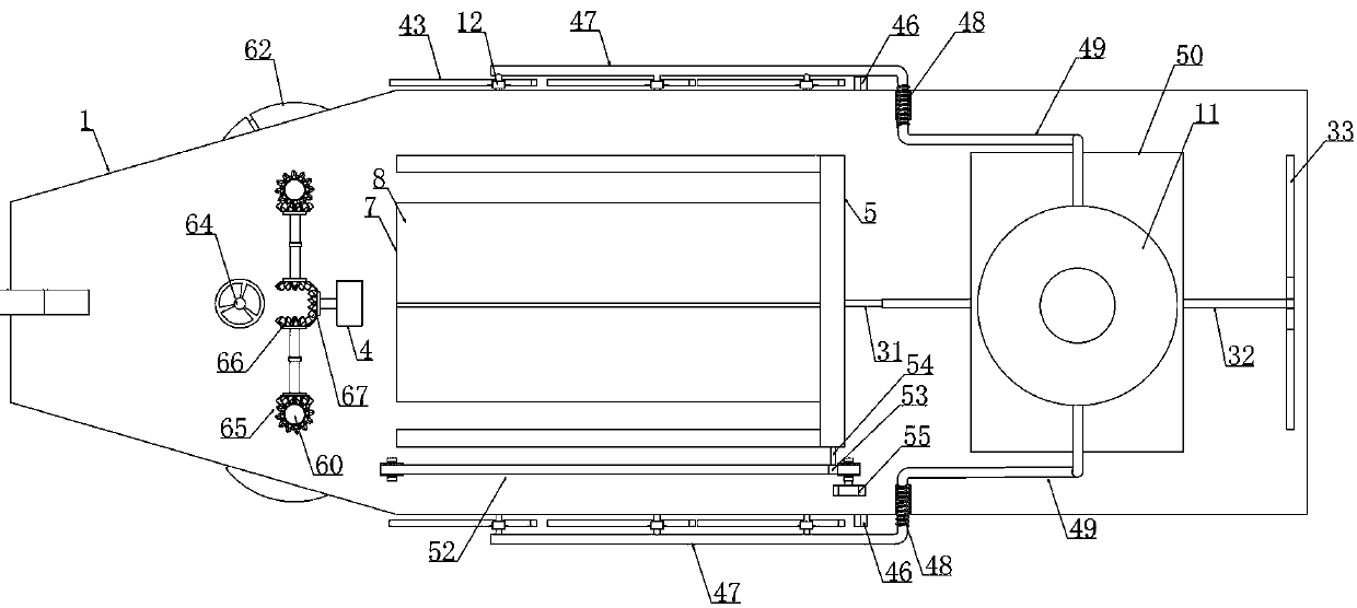
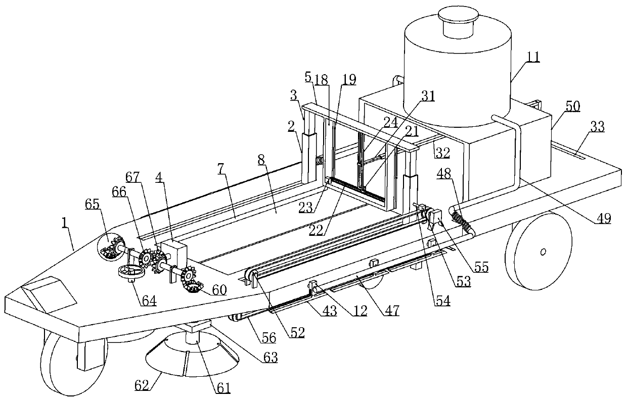
[0038] Embodiment 1, airport runway crack detection and maintenance equipment, including a trailer 1 and a tractor connected to the front of the trailer 1, it is characterized in that the upper end surface of the trailer 1 is longitudinally spaced and provided with a slider 2 that is slidably connected to the trailer 1 and slides Slider 3 is vertically slidably connected in cylinder 2, and described slider 2 is driven by the first driving device that is arranged on the upper end surface of trailer 1, and two sliders 2 upper ends are provided with vertically extending horizontal bar 5 and two sliders 3 are placed The outer end of the sliding cylinder 2 is respectively connected to the longitudinal sides of the crossbar 5, the lower end of the crossbar 5 is fixedly connected with a crack detection device and the crack detection device is electrically connected to a micro-controller processor, and the slide rod 3 is connected with it. A first return spring 6 is connected between t...

Embodiment 2

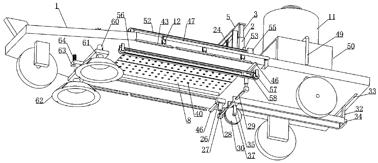
[0043]Embodiment 2, on the basis of Embodiment 1, rectangular sliding chambers 13 are respectively opened on the longitudinal side walls of the detection hole 7 and the protective plate 8 is slidably connected in the rectangular sliding chamber 13. The trigger device includes: The protective plate 8 is placed on the first conductive sheet on the side wall of the rectangular sliding cavity 13 and the bottom wall of the rectangular sliding cavity 13 is provided with a second conductive sheet matching the first conductive sheet, and the positioning device includes: the sliding cylinder 2 An electromagnet is provided on the inner bottom wall, and the electromagnet is connected in series with the first conductive sheet and the second conductive sheet in the voltage stabilizing circuit provided on the trailer 1, and an iron sheet is fixed at the bottom of the slide bar 3.

[0044] When this embodiment is in use, how the trigger device works will be described in detail below; Figure...

Embodiment 3

[0046] Embodiment 3, on the basis of Embodiment 2, a second chamber 14 extending longitudinally and spaced laterally from the two rectangular sliding chambers 13 is provided in the trailer 1 near the end of the cleaning device, and the third driving device includes: Two protective plates 8 are respectively connected with racks 15 at one end close to the cleaning device, and the racks 15 are longitudinally slidably connected in the second cavity 14, and the two racks 15 are jointly meshed with a gear 16 arranged in the second cavity 14 and The gear 16 is driven by an opening and closing motor 17 disposed in the second cavity 14 .

[0047] When this embodiment is in use, what constitutes about the third driving device and how to drive the two protective plates 8 to move will be described in detail below; Figure 10 , 15 As shown, two protective plates 8 are respectively connected with racks 15 near the ends of the cleaning device, and the racks 15 are longitudinally slidably co...


PUM


Abstract

The invention relates to airport runway crack detection and maintenance equipment. According to the airport runway crack detection and maintenance equipment, problems of low detection efficiency and low automation level of an existing airport runway crack detection device are effectively solved. The technical scheme for solving the problems is that a crack real-time monitoring device is arranged on a trailer; monitored data are transmitted to a micro-controller in real time; the micro-controller controls a grooving device to groove a rack according to the monitored crack data information; while the grooving device grooves the crack, protective plates are arranged on the trailer; during grooving, the two protective plates are closed to protect the crack detection device arranged on the trailer (damages of crushed stones and sand particles on the crack detection device during grooving can be avoided); while the grooving device grooves the crack, water in a water tank arranged on the trailer is sprayed to the grooving position through water spraying holes formed in the bottom walls of the protective plates; and therefore, larger dusts can be avoided during grooving.

Description

technical field [0001] The invention relates to the technical field of airport runway surface detection, in particular to an airport runway crack detection and maintenance equipment. Background technique [0002] In recent years, China's civil aviation industry has developed rapidly, and the total turnover of air transport has ranked second in the world. However, with the rapid growth of air traffic volume and the proportion of large-scale wide-body technology, some early-built airport runways may be in places with large temperature differences. The airport runway built in the area has serious damage to the pavement structure. It is more common that there are many cracks on the runway pavement, and these cracks are usually vertical (due to the long construction time, such cracks are mostly caused by the subsidence of the roadbed and base) or transverse cracks (Because the temperature difference changes greatly throughout the year, such cracks are mostly caused by the shrinka...

Claims


Application Information

Patent Timeline
IPC IPC(8): E01C23/07E01C23/09
CPCE01C23/07E01C23/096
Inventor 魏晓刚李广慧谢祥兵李亮
Owner ZHENGZHOU UNIVERSITY OF AERONAUTICS
Why Eureka
Try Eureka