
Method for preventing cast-in-place pile cage floating and adopted reinforced concrete base

A technology of reinforced concrete and cast-in-place piles, applied in sheet pile wall, construction, infrastructure engineering and other directions, can solve problems such as unsatisfactory solutions, and achieve the effect of improving the quality of pile bottoms and ensuring reliable quality of pile bottoms

Pending Publication Date: 2019-08-20
GUIZHOU CONSTR SCI RES & DESIGN INST OF CSCEC
View PDF0 Cites 1 Cited by
  • Summary
  • Abstract
  • Description
  • Claims
  • Application Information

AI Technical Summary

Problems solved by technology

Therefore prior art scheme is not very ideal

Method used


Image

  • Method for preventing cast-in-place pile cage floating and adopted reinforced concrete base
  • Method for preventing cast-in-place pile cage floating and adopted reinforced concrete base

Examples


Embodiment

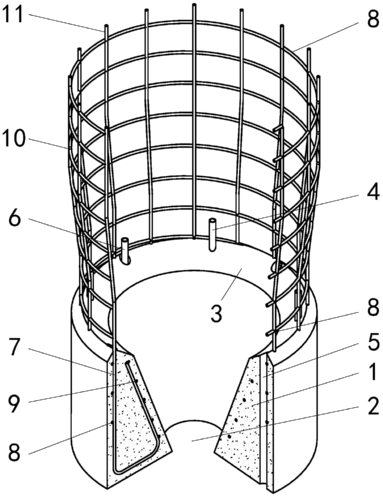
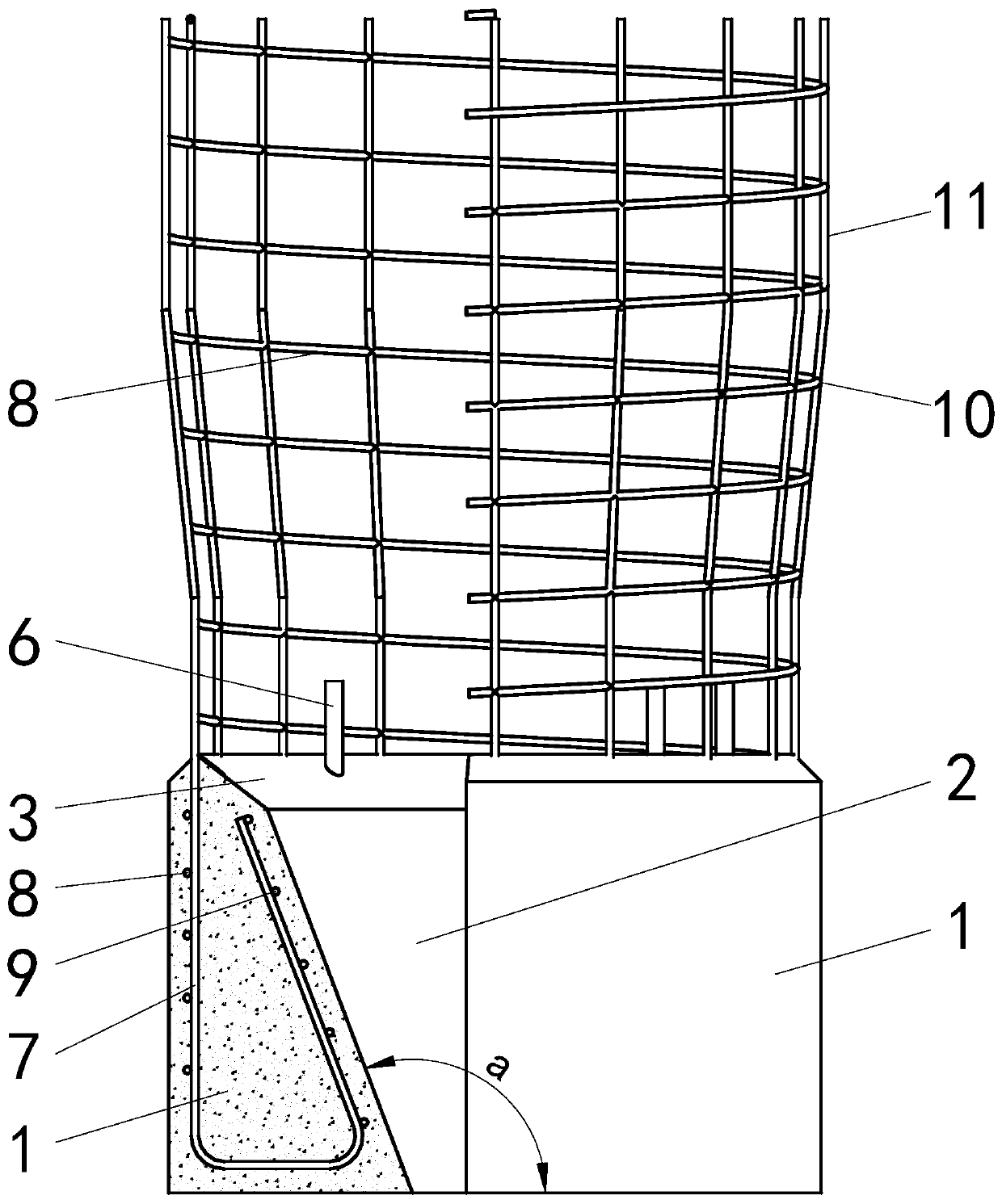
[0025] This example figure 1 and figure 2 As shown, the main rib 7 is included, and the main rib 7 is a hook-shaped steel bar, which is similar in shape to a right triangle. The number and diameter of the main reinforcement 7 are the same as the number of the longitudinal reinforcement 11 on the reinforcement cage 10 . After the processing of the main reinforcement 7 is completed, all the main reinforcement 7 are bound or welded as a whole through the spiral stirrup 8 and the ring reinforcement 9 . After the steel bars are connected, set up the formwork according to the size of the cast-in-place pile, and install the acoustic tube 2 and the grouting tube 6, and then pour the reinforced concrete base 1. The strength grade of the concrete used for the reinforced concrete base 1 is not lower than C30, which is the design strength The larger of the grades. The reinforced concrete base 1 can only be connected with the steel cage 10 after the solidification period reaches 28 day...


PUM


Abstract

The invention discloses a method for preventing cast-in-place pile cage floating and an adopted reinforced concrete base. The reinforced concrete base is welded to the bottom of a reinforcing cage ofa cast-in-place pile, and a middle hole of the reinforced concrete base is arranged to be in a shape of a hopper with the large top and the small bottom; when pile concrete is poured, gravity of the concrete enables the reinforced concrete base to generate downward pulling force, and therefore the cage floating phenomenon is prevented. According to the method, the downward force is generated through the reinforced concrete base, and cage floating can be prevented; the bottom surface of the reinforced concrete base is in contact with the bottom surface of a pile hole, and upward floating forcegenerated by impact of the poured concrete basically has no influence on a pile bottom section; the reinforced concrete base has the strengthening effect on the pile bottom, the quality of the pile bottom can be improved, certain guarantees are provided, and the pile bottom quality is reliably guaranteed after a grouting pipe is used for secondary reinforcement on the pile bottom.

Description

technical field [0001] The invention relates to a method for preventing the floating cage of cast-in-place piles and a reinforced concrete base used therefor, and belongs to the technical field of building construction. Background technique [0002] During the construction of cast-in-situ piles, when the bottom of the pile body is located in the groundwater or the mud retaining wall, the construction quality of the pile foundation is difficult to control. The reason is that the groundwater or mud at the bottom of the pile has buoyancy to the pile foundation, which is called the floating cage phenomenon. If there is a floating cage phenomenon during the concrete pouring process, it will cause segregation at the bottom of the pile. [0003] The prior art usually adopts pile bottom grouting or the method of adding steel pipe piles at the pile bottom; in order to prevent floating cage phenomenon. The main methods are to adjust the specific gravity of the mud, control the slump...

Claims


Application Information

Patent Timeline
Patent Type & Authority Applications(China)
IPC IPC(8): E02D5/34
CPCE02D5/34
Inventor 谭祖彪帅海乐
Owner GUIZHOU CONSTR SCI RES & DESIGN INST OF CSCEC
Learn More