Eureka AIR delivers breakthrough ideas for toughest innovation challenges, trusted by R&D personnel around the world.

Upward-sloping drainage structure with self-anchoring function and construction method thereof

A technology of drainage structure and construction method, applied in basic structure engineering, excavation, construction, etc., can solve the problems of cumbersome construction process, long construction period and high cost, and achieve the effects of convenient construction, improved pullout resistance and strong adaptability

Pending Publication Date: 2019-08-20
CHINA MERCHANTS CHONGQING COMM RES & DESIGN INST
View PDF0 Cites 2 Cited by
  • Summary
  • Abstract
  • Description
  • Claims
  • Application Information

AI Technical Summary

Problems solved by technology

The existing treatment methods are usually to drill vertically inclined drainage holes and anchor holes for reinforcing the anchor rods (cables) on the rock and soil to be reinforced. The drilling operation is repeated, and the following steps are required Anchor (cable), pouring and anchoring operations, the construction process is cumbersome, the construction period is long, and the cost is high

Method used


Image

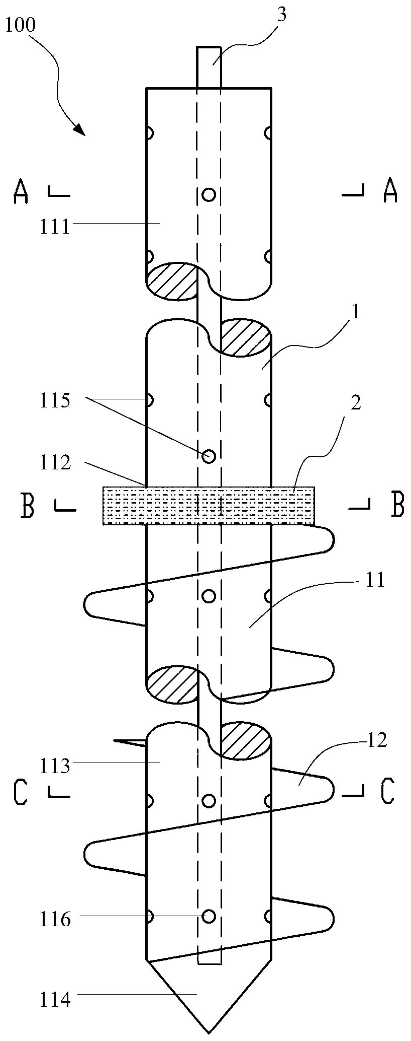
  • Upward-sloping drainage structure with self-anchoring function and construction method thereof
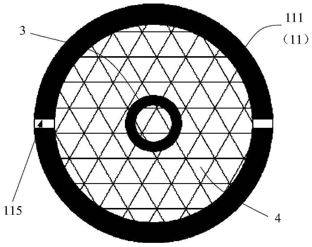
  • Upward-sloping drainage structure with self-anchoring function and construction method thereof
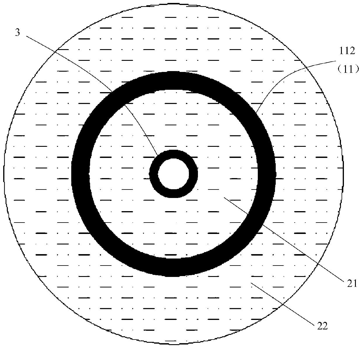
  • Upward-sloping drainage structure with self-anchoring function and construction method thereof

Examples


Embodiment Construction

[0038] Embodiments of the technical solutions of the present invention will be described in detail below in conjunction with the accompanying drawings. The following examples are only used to illustrate the technical solutions of the present invention more clearly, and therefore are only examples, rather than limiting the protection scope of the present invention. In the description of the present application, it should be understood that the orientation or positional relationship indicated by the terms "upper", "lower", "front", "rear", "left", "right" etc. is based on the drawings The orientation or positional relationship shown is only for the convenience of describing the present invention and simplifying the description, but does not indicate or imply that the components or structures referred to must have a specific orientation, be constructed and operated in a specific orientation, and therefore cannot be construed as limiting the scope of the present invention. limit. ...


PUM


Abstract

The invention discloses an upward-sloping drainage structure with a self-anchoring function. The upward-sloping drainage structure with the self-anchoring function comprises an anchor pipe main body,a water stop body and a grouting pipe; the anchor pipe main body comprises a steel pipe body and a spiral cutter edge; the steel pipe body is divided into a drainage section, a water stop section, ananchoring section and a pile tip which are connected in sequence in the axial direction; a plurality of drainage holes are formed in the pipe wall of the drainage section; a water filtering body is placed in the pipe cavity of the drainage section; a plurality of grouting holes are formed in the pipe wall of the anchoring section; the spiral cutter edge is arranged on the outer pipe wall of the anchoring section in a surrounding manner in a spiral strip shape; the water stop body comprises an inner water stop body and an inner water stop body; the inner water stop body is arranged in the pipecavity of the water stop body; the outer water stop body is arranged on the outer pipe wall of the water stop section annularly; the grouting pipe is arranged in the pipe cavity of the steel pipe body; one end of the grouting pipe is positioned in the anchoring section; and the other end of the grouting pipe penetrates through the inner water stop body and extends out of the end surface of the drainage section. Meanwhile, a matched construction method is provided to simplify the draining and anchoring operation in slope protection, facilitate construction, shorten the working period and reducethe cost.

Description

technical field [0001] The invention relates to the technical fields of slope protection, dangerous rock treatment, deep foundation pit support, tunnel and underground engineering drainage support, in particular to an inclined drainage structure with a self-anchoring function and a construction method thereof. Background technique [0002] In the process of slope protection, dangerous rock treatment, deep foundation pit support, tunnel and underground engineering drainage support, it is necessary to carry out drainage and anchorage treatment on the rock and soil near the sliding surface or rupture surface, and unfavorable structural surface, so as to avoid Or reduce geological problems or diseases such as slipping, falling, toppling, and falling blocks in rock and soil. The existing treatment methods are usually to drill vertically inclined drainage holes and anchor holes for reinforcing the anchor rods (cables) on the rock and soil to be reinforced. The drilling operation i...

Claims


Application Information

Patent Timeline
Patent Type & Authority Applications(China)
IPC IPC(8): E02D17/04E02D17/20E02D19/06
CPCE02D17/04E02D17/20E02D17/207E02D19/06
Inventor 柴贺军冯彦铭李海平唐胜传阎宗岭贾学明单荣相徐建强苟栋元徐峰
Owner CHINA MERCHANTS CHONGQING COMM RES & DESIGN INST
Why Eureka
Eureka Blog
Learn More