Turbine rotor fork-shaped blade mounting structure and mounting method thereof

A technology for the installation of steam turbine rotors and blades. It is applied to the supporting elements, mechanical equipment, and engine elements of blades. It can solve the problems of weak installation structure and easy existence of gaps, and achieve the effect of preventing loosening and ensuring installation firmness.

Active Publication Date: 2019-08-20
浙江合泰热电有限公司
View PDF8 Cites 7 Cited by
  • Summary
  • Abstract
  • Description
  • Claims
  • Application Information

AI Technical Summary

Problems solved by technology

[0006] The above existing technical solutions have the following defects: after all the blades are installed, the last blade needs to be locked, and when the blade root of the last blade is inserted into th

Method used


Image

  • Turbine rotor fork-shaped blade mounting structure and mounting method thereof
  • Turbine rotor fork-shaped blade mounting structure and mounting method thereof
  • Turbine rotor fork-shaped blade mounting structure and mounting method thereof

Examples


Embodiment 1

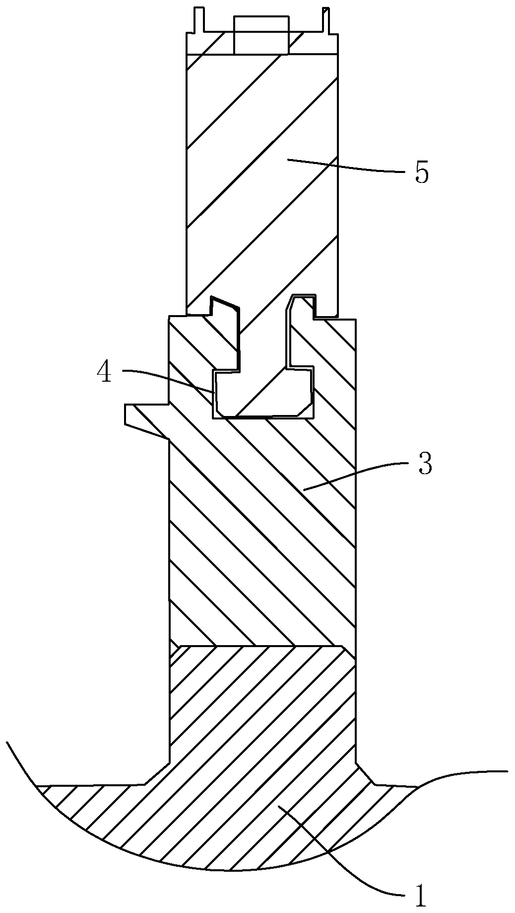
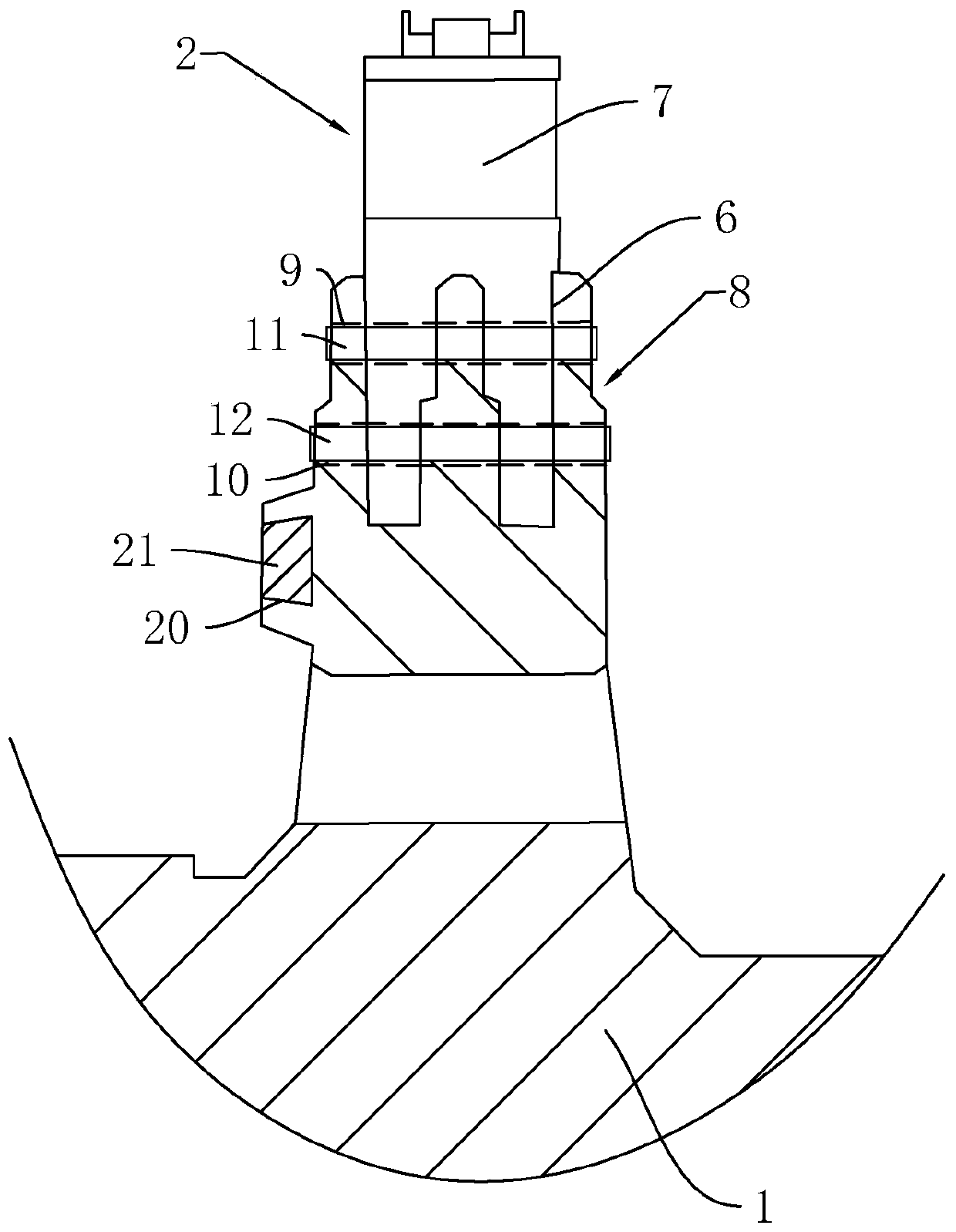
[0048] refer to figure 1 and figure 2 , is a steam turbine rotor fork-shaped blade installation structure disclosed in the present invention, including a rotor 1 and a fork-shaped blade 2 connected to the periphery of the rotor 1, and a mounting seat 3 is integrally formed on the side wall of the rotor 1, and the mounting seat 3 is annular. And coaxial with the rotor 1, a fork-shaped wheel groove 4 is provided, and a number of intermediate blades 5 are slidably engaged in the fork-shaped wheel groove 4, and the blade roots of the intermediate blades 5 are slidably engaged in the fork-shaped wheel groove 4. The side wall of the wheel groove 4 is provided with a wheel groove 6 along the radial direction of the rotor 1, and the last blade 7 is pierced in the wheel groove 6, and a locking assembly for locking the last blade 7 is also arranged on the wheel groove 6 8. After inserting the middle blade 5 into the fork-shaped wheel groove 4, slide the middle blade 5 so that several ...

Embodiment 2

[0055] A method for installing a steam turbine rotor fork-shaped blade, comprising the following steps,

[0056] S1, insert the blade roots of the middle sheets through the wheel groove 6 in turn, and then slide inward along the fork-shaped wheel groove 4, so that the blade roots of several middle sheets are arranged closely, and the fork-shaped wheel grooves are arranged in 4 rows through the middle sheets Full;

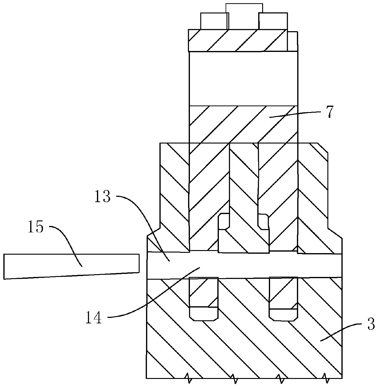
[0057] S2, such as image 3 As shown, a first prefabricated hole 13 is provided on the side wall of the wheel groove 6 on the mounting seat 3, and a second prefabricated hole 14 corresponding to the first prefabricated hole 13 is provided at the root of the last blade 7. The aperture of the second prefabricated hole 14 is greater than or equal to the diameter of the first prefabricated hole 13;

[0058] S3, insert the blade root of the last blade 7 into the wheel groove 6, at this time there is a gap between the lower surface of the blade root of the last blade 7 ...


PUM


Abstract

The invention discloses a turbine rotor fork-shaped blade mounting structure, and relates to the technical field of turbine blade installation. The invention aims to solve the problem that a mountingclerance cannot be eliminated when a traditional mounting blade is installed. The turbine rotor fork-shaped blade mounting structure is characterized by comprising a rotor and a fork-shaped blade connected to the rotor, a mounting seat is connected to the side wall of the rotor, an annular fork-shaped wheel groove is coaxially formed in the mounting seat and the rotor, a plurality of middle bladesare slidably clamped in the fork-shaped wheel groove, wheel grooves are formed in the side walls of the fork-shaped wheel grooves in the radial direction of the rotor, tail blades are arranged in thewheel grooves in a penetrating mode, and locking assemblies used for locking the tail blades are arranged in the wheel grooves. The turbine rotor fork-shaped blade mounting structure has the advantages of being simple and firm to mount and capable of effectively eliminating the mounting clearance.

Description

technical field [0001] The invention relates to the technical field of steam turbines, in particular to a steam turbine rotor fork-shaped blade installation structure and an installation method thereof. Background technique [0002] The steam turbine, also known as the steam turbine engine, is a rotary steam power device. The high-temperature and high-pressure steam passes through the fixed nozzle to become an accelerated air flow and then sprays onto the blades, so that the rotor equipped with blade rows rotates and works externally. Steam turbines are the main equipment of modern thermal power plants, and are also used in metallurgical industry, chemical industry, and ship power plant. [0003] The airfoil is the working part of the blade, and the airflow channel is formed between the airfoil parts of adjacent blades, and the kinetic energy is converted into mechanical energy when the steam flows through. According to the changing law of the cross-section of the blade sha...

Claims


Application Information

Patent Timeline
IPC IPC(8): F01D5/30F01D5/32
CPCF01D5/3007F01D5/326
Inventor 王重伟
Owner 浙江合泰热电有限公司
Why Eureka
Try Eureka