Low-temperature storage tank vault low-temperature pipeline sleeve cold insulating structure and mounting method thereof

A low-temperature storage tank and vault technology, which is applied to the installation device of container structure, container filling method, container discharge method, etc., can solve the problems of thermal insulation and cold leakage, construction and installation, etc. The effect of safety and reliability

Active Publication Date: 2019-08-20
CHINA NAT AIR SEPARATION ENG CO LTD
View PDF7 Cites 0 Cited by
  • Summary
  • Abstract
  • Description
  • Claims
  • Application Information

AI Technical Summary

Problems solved by technology

[0003] In order to solve the problems existing in the prior art, the present invention provides a cold storage structure and installation method for the low-temperature pipeline sleeve of the vault of the low-temperature storage tank, which is used to solve the problem of heat insulation leakage and cold of the low-temperature pipeline sleeve of the vault of the large low-temperature storage tank. Construction and installation problems

Method used


Image

  • Low-temperature storage tank vault low-temperature pipeline sleeve cold insulating structure and mounting method thereof
  • Low-temperature storage tank vault low-temperature pipeline sleeve cold insulating structure and mounting method thereof
  • Low-temperature storage tank vault low-temperature pipeline sleeve cold insulating structure and mounting method thereof

Examples


Embodiment Construction

[0027] The present invention will be further described below in conjunction with the accompanying drawings of the description.

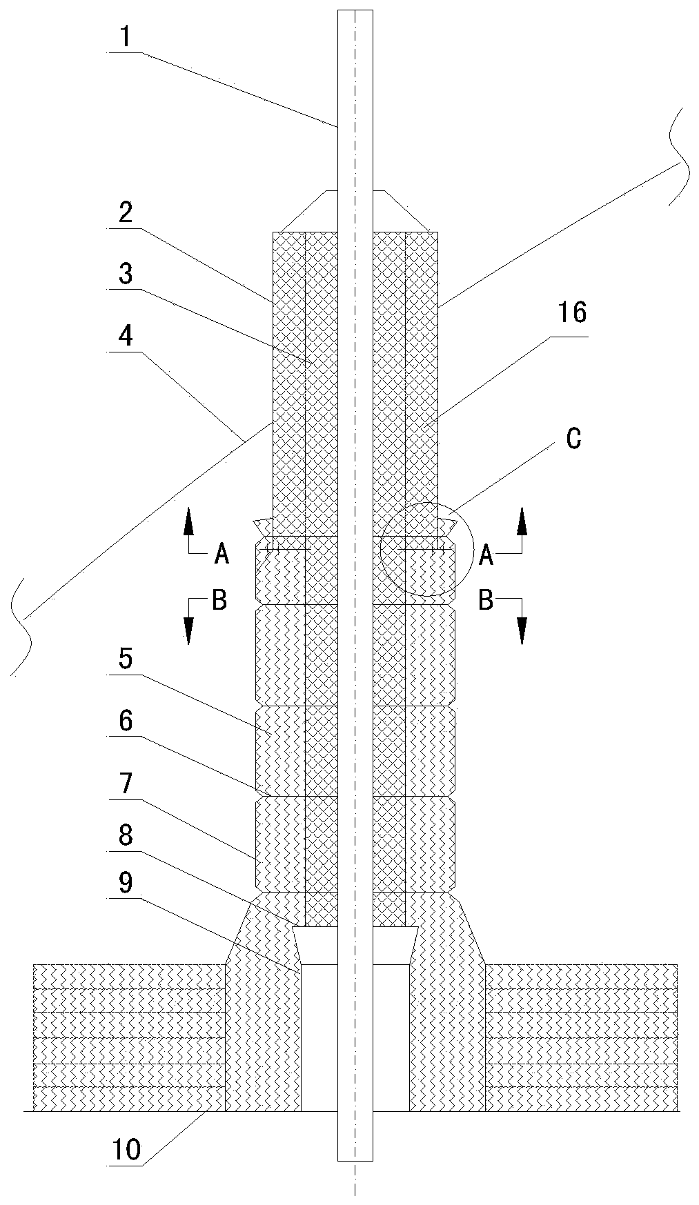
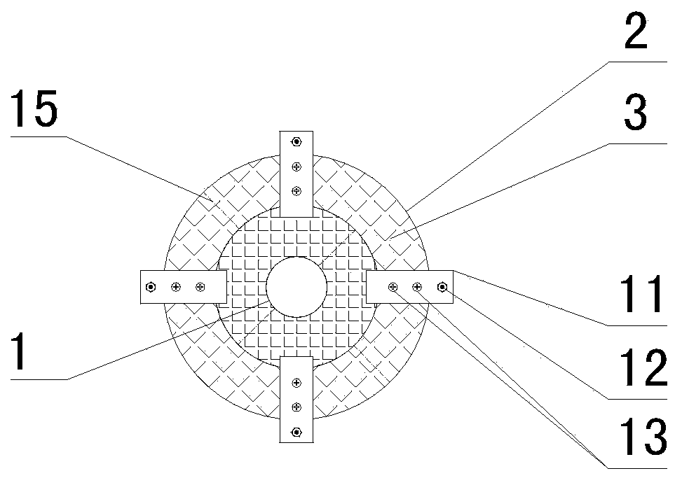
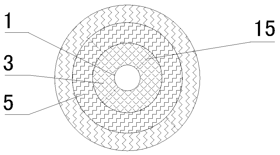
[0028] Such as Figure 1-9 As shown, a cryogenic storage tank vault cryogenic pipe sleeve cold insulation structure, including cryogenic pipe 1, vault sleeve 2, PIR prefabricated block 3, outer tank vault 4, glass wool 5, stainless steel wire 6, glass fiber cloth 7. Support plate 8, ceiling sleeve 9, inner tank ceiling 10, clamping plate 11, bolts and nuts 12, self-tapping screws 13, fixing plate 14, low-temperature glue 15 and outer PIR prefabricated block 16.

[0029] The cold-insulation structure of the low-temperature pipeline sleeve on the vault of the low-temperature storage tank includes the outer tank vault 4, the inner tank ceiling 10, and the low-temperature pipeline 1 pierced between the outer tank vault 4 and the inner tank ceiling 10. The upper end of the low-temperature pipeline 1 is provided with The vault sleeve 2, the lower end of t...


PUM


Abstract

The invention discloses a low-temperature storage tank vault low-temperature pipeline sleeve cold insulating structure and a mounting method thereof. The low-temperature storage tank vault low-temperature pipeline sleeve cold insulating structure comprises an outer tank vault, an inner tank ceiling, and a low-temperature pipeline which is arranged between the outer tank vault and the inner tank ceiling in a penetrating manner; a vault sleeve is arranged at the position at the upper end of the low-temperature pipeline; a ceiling sleeve is arranged at the lower end of the low-temperature pipeline; a supporting plate is arranged above the ceiling sleeve; an inner PIR precast block is arranged at the position, between the top end of the vault sleeve and the supporting plate, outside the low-temperature pipeline in a sleeving manner; an outer PIR precast block is arranged between the vault sleeve and the inner PIR precast block; the low-temperature storage tank vault low-temperature pipeline sleeve cold insulating structure and the mounting method thereof have the beneficial effects that the structure is good in cold insulating effect and convenient to mount; the problem of leakage caused by settlement in a long-term operating process of the structure that the sleeve is filled with conventional glass wool is effectively solved; meanwhile, the problem that the structure that an in-situ foamed insulating material is used in the sleeve is also solved; and the safety and the reliability of a local structure are improved.

Description

technical field [0001] The invention relates to the technical field of large-scale low-temperature storage tanks, in particular to a cold-preservation structure of a low-temperature pipeline sleeve on a vault of a low-temperature storage tank and an installation method thereof. Background technique [0002] More and more large-scale low-temperature storage tanks are used in the energy and petrochemical industries. These large-scale low-temperature storage tanks mostly adopt a vertical cylindrical structure at atmospheric pressure, and the inlet and outlet of the pipelines are all set on the top of the tank. With the use of the storage tank, the traditional glass wool-filled sleeve structure will settle during long-term operation due to its own gravity and the non-rebound of its own material, which will lead to cold leakage. foam insulation material structure and installed on the outer tank vault as a whole, but for double-layer metal low-temperature storage tanks, the sleeve...

Claims


Application Information

Patent Timeline
Patent Type & Authority Applications(China)
IPC IPC(8): F17C13/00
CPCF17C13/00F17C2205/03F17C2209/22F17C2209/23Y02E60/32
Inventor 江炜李积杰周思雯方其邵先胜杜春波魏强郑宏华雷晓林冯广明赵方华
Owner CHINA NAT AIR SEPARATION ENG CO LTD
Why Eureka
Try Eureka