Fuel pluger pump for internal combustion ingine

A plunger pump, plunger technology, applied in the field of perfect plunger pump, can solve problems such as surface sticking

Inactive Publication Date: 2003-02-12
ROBERT BOSCH GMBH
View PDF2 Cites 2 Cited by
  • Summary
  • Abstract
  • Description
  • Claims
  • Application Information

AI Technical Summary

Problems solved by technology

In fact, this kind of pressure squeezes the oil film of fuel or lubricating oil between the contact surfaces, so that the fuel or lubricating oil is squeezed out of the corresponding gap, which will cause the two surfaces to seize.

Method used


Image

  • Fuel pluger pump for internal combustion ingine
  • Fuel pluger pump for internal combustion ingine
  • Fuel pluger pump for internal combustion ingine

Examples


Embodiment Construction

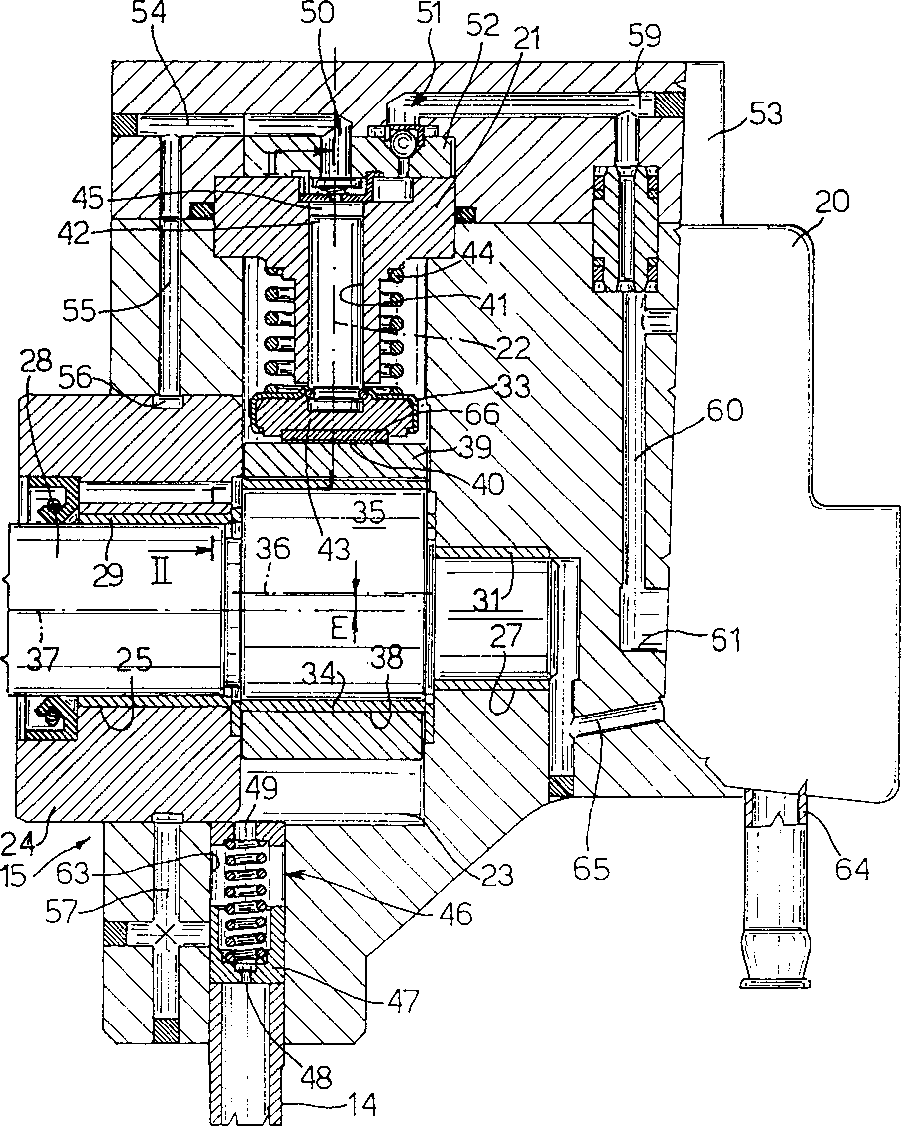
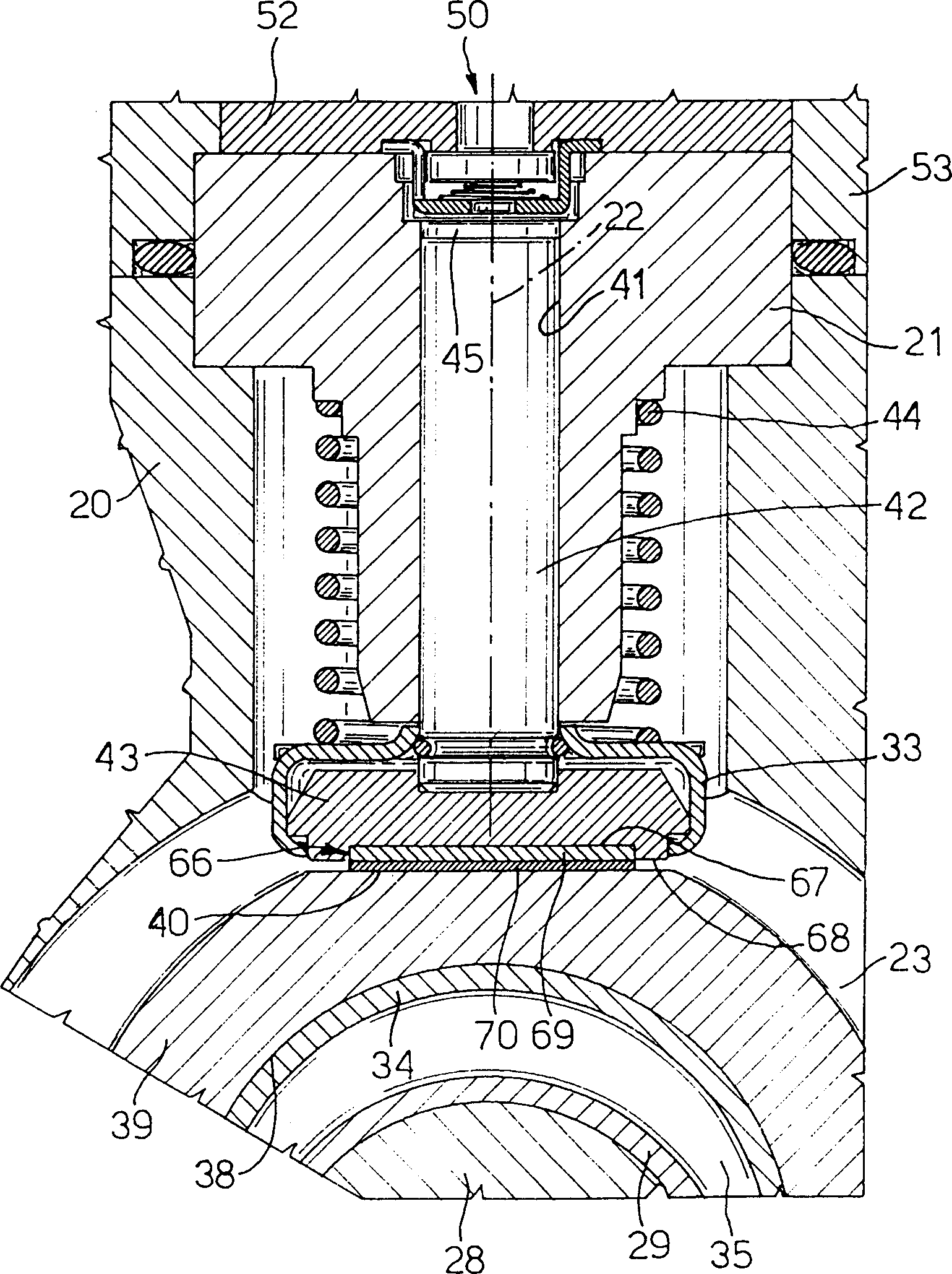
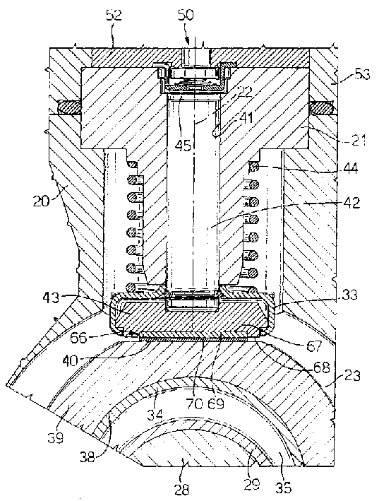
[0013] figure 1 The reference numeral 15 in represents a high-pressure radial piston pump, which is used to provide fuel to an internal combustion engine such as a diesel engine. The piston pump includes three cylinders 21, which are radially arranged in the housing 20, and the clamping between their respective axes 22 The angular interval is 120°. In the center, the housing 20 comprises a cup-shaped interior 23 which is closed by a flange 24 .

[0014] The pump 15 comprises a drive shaft 28 having two parts fitted with respective sliding bearings 29 and 30, through which the shaft 28 rotates in the hole 25 of the flange 24 and in the blind hole 27 of the housing 20; 28 is integrated with the eccentric part 35, and the eccentric part is installed in the cavity 23, and another sliding bearing 34 is assembled, and this sliding bearing cooperates with the inner surface of the hole 38 of the annular cam 39, and the cam controls the pump 15, and the cam 39 is in the eccentric part...


PUM


Abstract

A piston pump for internal combustion engine has a number of cylinders arranged with their respective axes at a predetermined angular distance about a drive shaft; and a number of pistons, each sliding inside a respective cylinder. The inner radial end of each piston is fitted with a pad engaging a respective flat portion of a cam rotating on an the drive shaft; and, to ensure against seizure, each pad has a cavity inside which is fitted a shoe having at least one layer of self-lubricating material engaging the respective flat portion of the cam.

Description

technical field [0001] The present invention relates to a perfect plunger pump, in particular a plunger pump for supplying oil to an internal combustion engine. Background technique [0002] It is well known that in internal combustion engines, especially in diesel engines, the working pressure of the above-mentioned type of pump even exceeds 1300 bar, and its working speed is also as high as about 3000 rpm. [0003] The cylinders of a plunger pump of the type described above are arranged radially around a drive shaft comprising an eccentric portion on which the cams for actuating the cylinders rotate, each cylinder comprising a pad which is aligned with the corresponding cam Flat parts are joined. When in use, the eccentric part drives the cam so that it moves parallel to itself at all times, and its motion trajectory is a circle, so that each liner slides smoothly on the corresponding plane part, and there is no swing of the angle of the corresponding plunger axis . [...

Claims


Application Information

Patent Timeline
IPC IPC(8): F02M59/06A61C9/00F02M59/10F02M59/44F02M63/00F04B1/04F04B1/053F04B9/04F04B39/00
CPCF04B1/0408F02M63/0001F04B1/053F04B1/0426F02M37/04
Inventor 马里奥·里科
Owner ROBERT BOSCH GMBH
Why Eureka
Try Eureka