Impeller structure of artificial heart pump

A technology of artificial heart and pump impeller, applied in blood pumps, blood pumps, hypodermic injection devices, etc., can solve the problems of low efficiency, large speed and volume of single-stage centrifugal pumps, and achieve low hemolysis and thrombosis probability and high volume. Efficiency and the effect of a small number of parts

Pending Publication Date: 2022-07-08
INST OF ELECTRICAL ENG CHINESE ACAD OF SCI
View PDF0 Cites 0 Cited by
  • Summary
  • Abstract
  • Description
  • Claims
  • Application Information

AI Technical Summary

Problems solved by technology

[0005] In the field of artificial heart pumps, there are mainly two types of centrifugal pumps and axial flow pumps, each with its own advantages and disadvantages. Due to the excellent properties of centrifugal pumps, almost all third-generation artificial heart pumps use centrifugal pumps, but the single-stage centrifugal pump efficiency Lower speed and larger volume

Method used


Image

  • Impeller structure of artificial heart pump
  • Impeller structure of artificial heart pump
  • Impeller structure of artificial heart pump

Examples


Embodiment 1

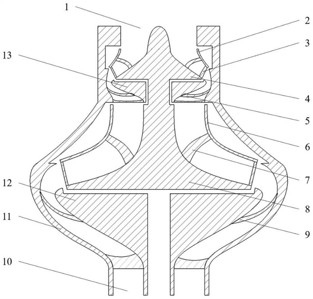
[0034] This embodiment provides an artificial heart pump impeller structure, such as Figure 1-3 As shown, the impeller structure includes the first-stage centrifugal pump upper cover 2, the first-stage centrifugal pump blades 3, the first-stage centrifugal pump guide cone 4, the second-stage centrifugal pump upper cover 6, the second-stage centrifugal pump Pump vane 7, second-stage centrifugal pump guide cone 8 and casing. Wherein, the bottom surface portion of the first-stage centrifugal pump guide cone 4 and the second-stage centrifugal pump guide cone 8 also serve as the lower cover plate of each stage of impeller. In addition to the outer casing 11, the casing also includes the first-stage guide vanes 5, the second-stage guide vanes A 9, the guide cones 12 of the second-stage guide vanes A, and the guide vanes of the first-stage guide vanes fixed thereon. Cone 13. The housing is divided into left and right parts, and the combination of the left housing and the right hou...

Embodiment 2

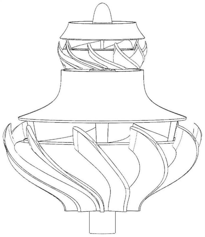
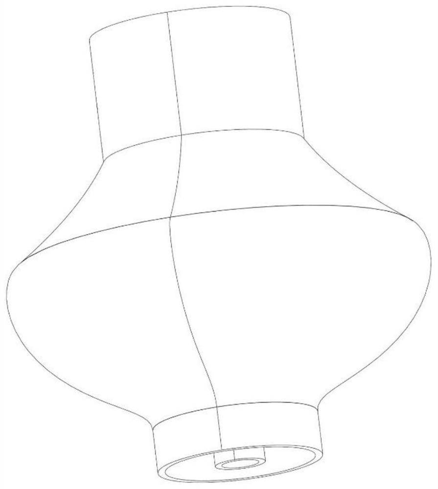
[0039] This embodiment provides a second artificial heart pump impeller structure, such as Figure 4-5 As shown, compared with Embodiment 1, the outlet of the second-stage centrifugal pump vane 7 is not inclined, and does not have the second-stage guide vane A 9 and the guide cone 12 of the second-stage guide vane A, and the casing is made Adjustment. The shell of this embodiment 2 is still divided into two parts: left and right. After the two parts are combined, an inner chamber and an inlet 1 are formed. The outlet 10 is located on the right half of the shell. The half part is constructed in the form of a volute as the kinetic energy conversion device of the last stage impeller. The internal structure of this embodiment is as follows Figure 4 shown, the overall appearance is as Figure 5 shown.

[0040] In this embodiment, the blood flows in from the inlet 1 of the pump body, and the first half of the blood flowing through is the same as that in Embodiment 1, except tha...

Embodiment 3

[0042] like Figure 6-7 As shown, compared with Embodiment 2, this embodiment only adds the second-stage guide vane B14 to the outer ring of the second-stage centrifugal pump impeller, the second-stage guide vane B14 is fixed on the casing, and the appearance of the second-stage guide vane B14 like Figure 7 As shown, two types of guide vanes, open type and closed type, can be used, and the lower cover plate of the second-stage guide vane B14 in the figure is a part of the casing.

[0043] The blood flow in this embodiment is similar to that in Embodiment 2, except that the guide vane and the volute are used together as the kinetic energy conversion device of the second-stage impeller.


PUM


Abstract

The invention provides an impeller structure of an artificial heart pump, which comprises two groups of centrifugal pump blades, two centrifugal pump upper cover plates and two flow guide cones, and further comprises a corresponding shell which comprises an outer shell, one to two groups of guide blades and one to two flow guide cones, so that a special structure of the impeller structure is formed, and miniaturization and blood compatibility optimization of the artificial heart pump can be realized. The multi-stage centrifugal pump structure which is small in appearance and good in blood compatibility is adopted, the artificial heart pump structure which is simple and compact is constructed, the multiple centrifugal pump blades are connected in series in the structure, higher-efficiency blood pumping can be achieved in a more compact space, meanwhile, the flow guide cone structure is added, and the structure is more compact. The flow field structure of the heart pump can be effectively improved, good transition of flow fields of all centrifugal pumps is achieved, and blood compatibility is improved.

Description

technical field [0001] The invention belongs to the technical field of medical equipment, and in particular relates to an artificial heart pump impeller structure. Background technique [0002] Heart failure, referred to as heart failure, refers to a group of clinical syndromes in which venous return blood cannot be fully pumped from the heart due to myocardial dysfunction. Heart failure is mostly caused by various cardiovascular diseases. It is the end stage of heart disease development. The mortality rate and readmission rate are extremely high. The three-year readmission rate is higher than 50%, the five-year mortality rate is as high as 50%, and the ten-year mortality rate is as high as 50%. It is as high as 90%, which is comparable to malignant tumors or advanced cancers, and is considered to be a "fortress that has not been conquered in the cardiovascular field". According to the global epidemiological survey, in the world, on average, 3 to 5 people in every 100 peopl...

Claims


Application Information

Patent Timeline
Patent Type & Authority Applications(China)
IPC IPC(8): A61M60/122A61M60/216A61M60/232A61M60/806A61M60/804A61M60/855
CPCA61M60/122A61M60/216A61M60/232A61M60/806A61M60/804A61M60/855
Inventor 曲洪一孟令伟刘鑫王聪王秋良
Owner INST OF ELECTRICAL ENG CHINESE ACAD OF SCI
Why Eureka
Try Eureka