Preparation method of dissolved gas in transformer oil and preparation device

A technology of dissolving gas in oil and transformer oil, which is applied in the field of transformer oil and can solve problems such as vacancies

Active Publication Date: 2019-08-23
CHONGQING UNIV
View PDF3 Cites 0 Cited by
  • Summary
  • Abstract
  • Description
  • Claims
  • Application Information

AI Technical Summary

Problems solved by technology

[0003] At present, the detection of gas in oil has gradually become a research hotspot, but the preparation and device for the concentration of dissolved gas in oil tested by the sensor in oil are still in vacancy. The past devices were mai

Method used


Image

  • Preparation method of dissolved gas in transformer oil and preparation device
  • Preparation method of dissolved gas in transformer oil and preparation device
  • Preparation method of dissolved gas in transformer oil and preparation device

Examples


Embodiment 1

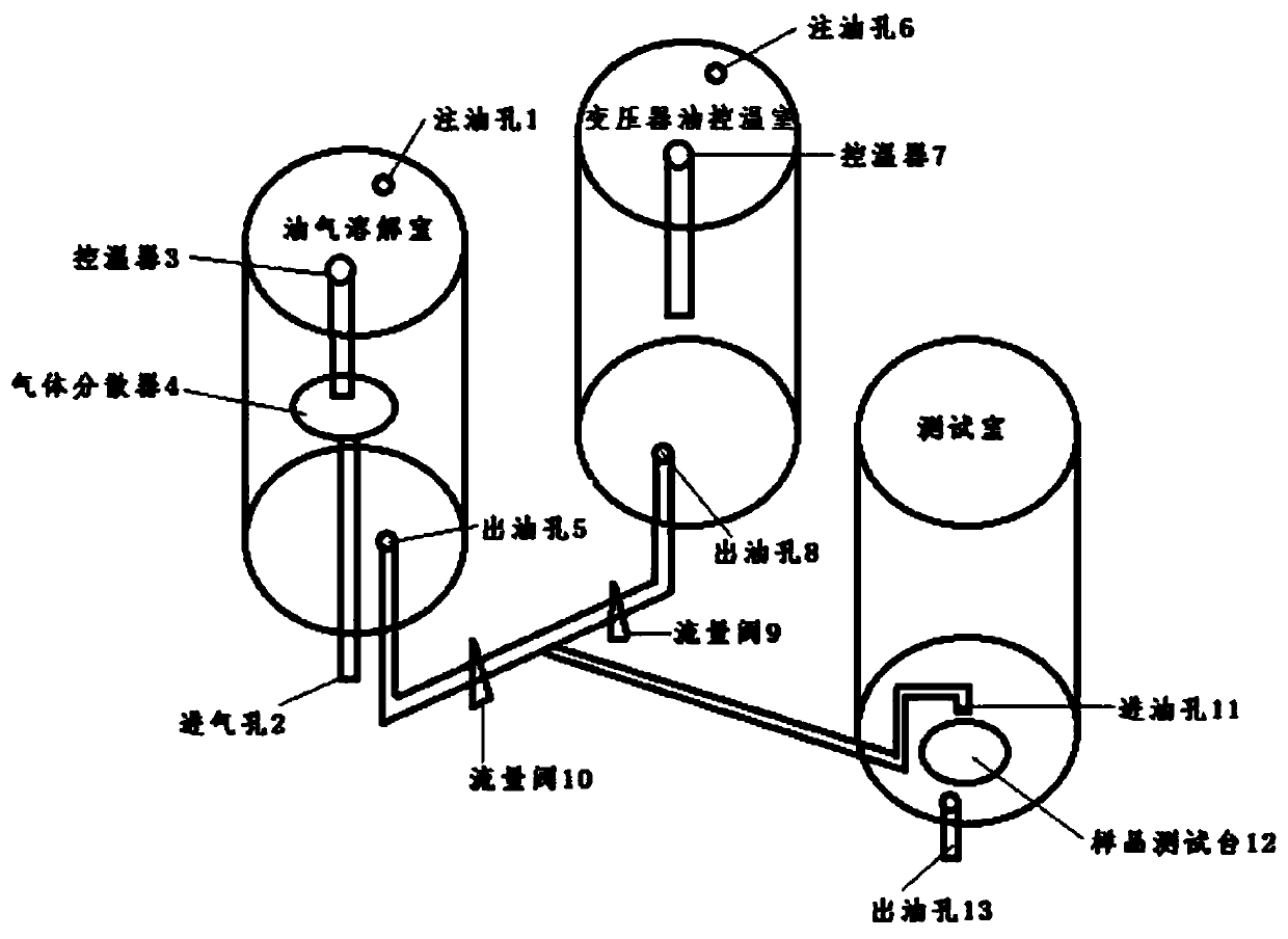
[0037] This embodiment 1 provides a preparation method for dissolved gas in transformer oil, which is to take two parts of the same transformer oil a and b, feed gas into transformer oil a to make the gas in a reach saturation, and then make the gas in a and b The temperature is the same, combined with the Ostwald coefficient derived from Henry's law to control the flow ratio of the oil in a and b, and finally prepare the transformer oil with a specified dissolved gas concentration.

[0038] As a further refinement, the Ostwald coefficient is dependent on temperature and its formula is:

[0039]

[0040] T: actual temperature;

[0041] L 0 : Ostwald coefficient of oil at 273K;

[0042] d: density of oil at 288K;

[0043] Calculated to get L c is the Ostwald coefficient at temperature T, so the dissolved gas concentration in the final formulated oil is:

[0044]

[0045] ω g : the gas concentration (%) passed into the oil;

[0046] Q g / o : the actual flow rate of ...

Embodiment 2

[0071] The purpose of Example 2 is to prepare transformer oils with dissolved gas concentrations in No. 10 transformer oil of 350 ppm, 480 ppm and 640 ppm under the condition of 80°C.

[0072] The specific operation process of this embodiment 2 is the same as that of embodiment 1.

[0073] The final calculation shows that when the dissolved gas concentrations in the transformer oil are 350ppm, 480ppm and 640ppm respectively, the flow control ratios in the oil-gas dissolution chamber and the transformer oil control greenhouse are respectively and

Embodiment 3

[0075] The purpose of Example 3 is to prepare transformer oils with dissolved gas concentrations of 50 ppm and 200 ppm in No. 25 and No. 45 transformer oils under the condition of 80° C., respectively.

[0076] The specific operation process of this embodiment 3 is the same as that of embodiment 1.

[0077] Finally, the flow control ratios in the oil-gas dissolution chamber and transformer oil control greenhouse of No. 25 transformer oil and No. 45 transformer oil are calculated as and


PUM


Abstract

The invention discloses a preparation method of a dissolved gas in transformer oil and a preparation device. The preparation method comprises the following steps: preparing transformer oil a and transformer oil b which are identical, introducing a gas into the transformer oil a till a saturation state of the gas, adjusting the transformer oil a and the transformer oil b till an identical temperature, controlling a flow ratio of the transformer oil a and the transformer oil b according to a Wilhelm Ostwald coefficient led by the Henry's law, and finally preparing transformer oil of an appointeddissolved gas concentration. The preparation device comprises an oil-gas dissolving chamber, a transformer oil temperature control chamber, a testing chamber and control equipment, wherein the oil-gas dissolving chamber, the transformer oil temperature control chamber and the testing chamber are respectively connected with the control equipment. The preparation method of the dissolving gas in thetransformer oil, which is disclosed by the invention, is good in practicability, controllable in operation method, simple in step and good in repeatability. The preparation device disclosed by the invention has a wide application range, and can be used as a preparation device of dissolved gas oil of various types of oil.

Description

technical field [0001] The invention relates to the technical field of transformer oil, in particular to a preparation method and a preparation device for dissolved gas in transformer oil. Background technique [0002] The monitoring of dissolved gas in transformer oil directly affects the accuracy of transformer fault diagnosis. The conventional analysis of dissolved gas in off-line oil in the laboratory is to regularly take oil samples on site and then analyze them on the laboratory chromatograph. The disadvantage is that the detection cycle is long , it is impossible to monitor the dissolved gas in the transformer oil in real time and effectively during the oil sampling cycle interval, and it is impossible to monitor the sudden failure of the transformer. The on-line monitoring system for dissolved gas in oil can realize continuous monitoring of transformer status, which is conducive to early detection of fault symptoms, especially effective in identifying sudden faults, ...

Claims


Application Information

Patent Timeline
IPC IPC(8): B01F15/04B01F15/00B01F3/04
CPCB01F23/23B01F35/2211B01F35/2215B01F35/833B01F2101/23
Inventor 王飞鹏胡克林刘洪呈杨力李剑黄正勇王有元陈伟根杜林万春香何渝霜王开正赵琦
Owner CHONGQING UNIV
Why Eureka
Try Eureka