
Laser arc side-shaft compounded surfacing machine and application method thereof

A laser arc, forming machine technology, applied in laser welding equipment, welding equipment, metal processing equipment and other directions, can solve the problem of unable to guarantee the forming effect, single direction, bottom-up forming and other problems

Pending Publication Date: 2019-08-23
XINJIANG UNIVERSITY
View PDF0 Cites 2 Cited by
  • Summary
  • Abstract
  • Description
  • Claims
  • Application Information

AI Technical Summary

Problems solved by technology

[0003] The invention provides a laser arc paraxial compound surfacing welding forming machine, aiming at the problems that the existing rapid prototyping machine can only form in one direction and from bottom to top, and cannot guarantee the forming effect for parts with special structures. The purpose of the present invention is to It is to realize the change of rapid prototyping position, so that it has better adaptability

Method used


Image

  • Laser arc side-shaft compounded surfacing machine and application method thereof
  • Laser arc side-shaft compounded surfacing machine and application method thereof
  • Laser arc side-shaft compounded surfacing machine and application method thereof

Examples


Embodiment Construction

[0027] The present invention is not limited by the following examples, and specific implementation methods can be determined according to the technical solutions of the present invention and actual conditions.

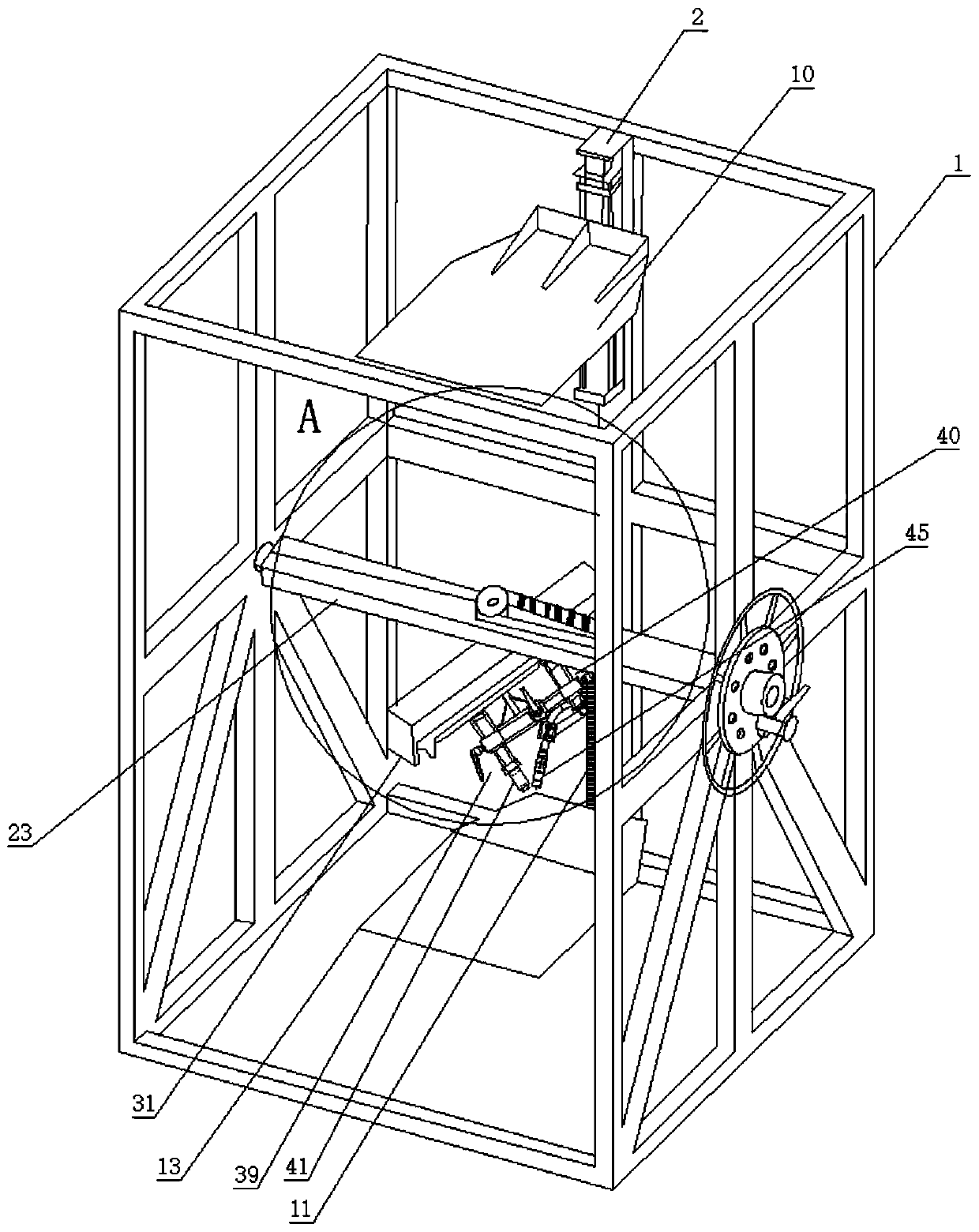
[0028] In the present invention, for the convenience of description, the description of the relative positional relationship of each component is based on the description attached to the description. figure 1 The layout method is described, such as: the positional relationship of front, back, up, down, left, right, etc. is based on the attached figure 1 determined by the layout direction.

[0029] Below in conjunction with embodiment and accompanying drawing, the present invention will be further described:

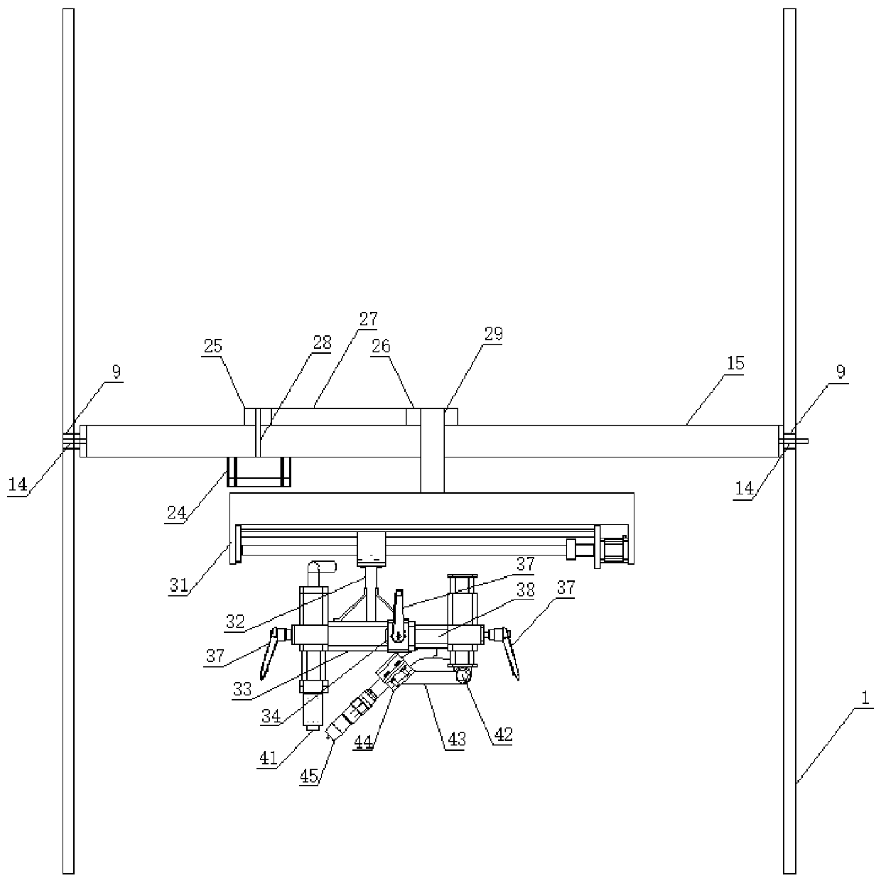
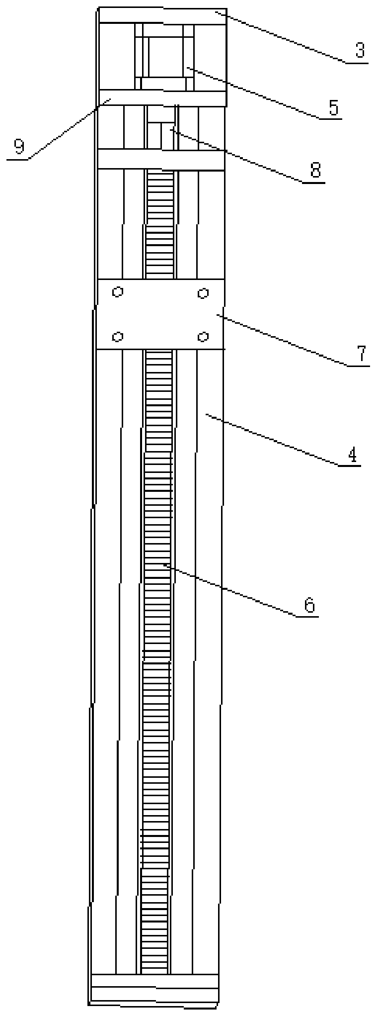
[0030] Such as Figure 1 to Figure 10 As shown, a laser arc paraxial composite surfacing welding forming machine includes a support frame 1, a first lifting device 2 is provided on the right side of the support frame 1, and the first lifting device 2 includes a ...


PUM


Abstract

The invention relates to the field of laser arc composite surfacing, in particular to a laser arc side-shaft compounded surfacing machine and an application method thereof. The design of a laser arc composite welding gun adopts a mode of side shaft compounding and guidance of arc by laser; the machine comprises an arc welding gun horizontal adjusting device, an arc welding gun vertical adjusting device, an arc welding gun angle adjusting device, an arc welding gun fixed frame, a laser welding gun fixed frame and a laser welding gun vertical adjusting device; the welding gun position and angleadjustment is realized; a polar coordinate mode is adopted to control; a revolving device is matched to realize a revolving motion to effectively guarantee uniform feeding speed in linear and curve motions; and the machine uses a laser arc compound quick molding technology to achieve high molding speed and good effect, realizes metal surfacing in 1G and 4G positions, can be used for molding partswith special structures, and is compact in overall structure, convenient to operate and high in working stability.

Description

technical field [0001] The invention relates to the field of laser arc composite surfacing welding, and relates to a laser arc paraxial composite surfacing forming machine and a use method thereof. Background technique [0002] Laser arc hybrid welding technology is often combined with rapid prototyping technology in modern mechanical production and has become an important part of metal 3D printing technology. Laser-arc composite rapid prototyping technology enables the heat source of laser and arc to act together on the forming area, and achieves a rapid prototyping method with higher efficiency, better quality and better performance than a single power source through the coupling of laser and arc. Among them, the addition of laser can improve the stability of the arc, and the rapid prototyping of wire arc can ensure the high efficiency of forming. However, the forming methods used by existing rapid prototyping machines rarely use laser arc compounding, and most of them us...

Claims


Application Information

Patent Timeline
Patent Type & Authority Applications(China)
IPC IPC(8): B23K26/348B23K26/342B23K26/70
CPCB23K26/348B23K26/702B23K26/342
Inventor 周建平薛瑞雷鲍阳许燕胡国玉海几哲何建斌毕元波董杰
Owner XINJIANG UNIVERSITY
Learn More