
Laser cutting system based on image recognition

A laser cutting and image recognition technology, applied in laser welding equipment, welding equipment, metal processing equipment and other directions, can solve the problems of low cutting production efficiency, large labor input, low cutting accuracy, etc., to improve cutting efficiency and reduce cutting costs. time, the effect of reducing data operations

Inactive Publication Date: 2019-08-23
JIANGSU UNIV
View PDF8 Cites 19 Cited by
  • Summary
  • Abstract
  • Description
  • Claims
  • Application Information

AI Technical Summary

Problems solved by technology

Some CNC cutting systems are combined with computer vision technology to recognize graphics, but for complex graphics, for example, there are N patterns in the graphics, it is difficult for such CNC cutting systems to accurately identify and plan the cutting path reasonably, resulting in cutting production Low efficiency, low cutting precision and large manpower input

Method used


Image

  • Laser cutting system based on image recognition
  • Laser cutting system based on image recognition

Examples


Embodiment Construction

[0039] The present invention will be further described below in conjunction with the accompanying drawings and specific embodiments, but the protection scope of the present invention is not limited thereto.

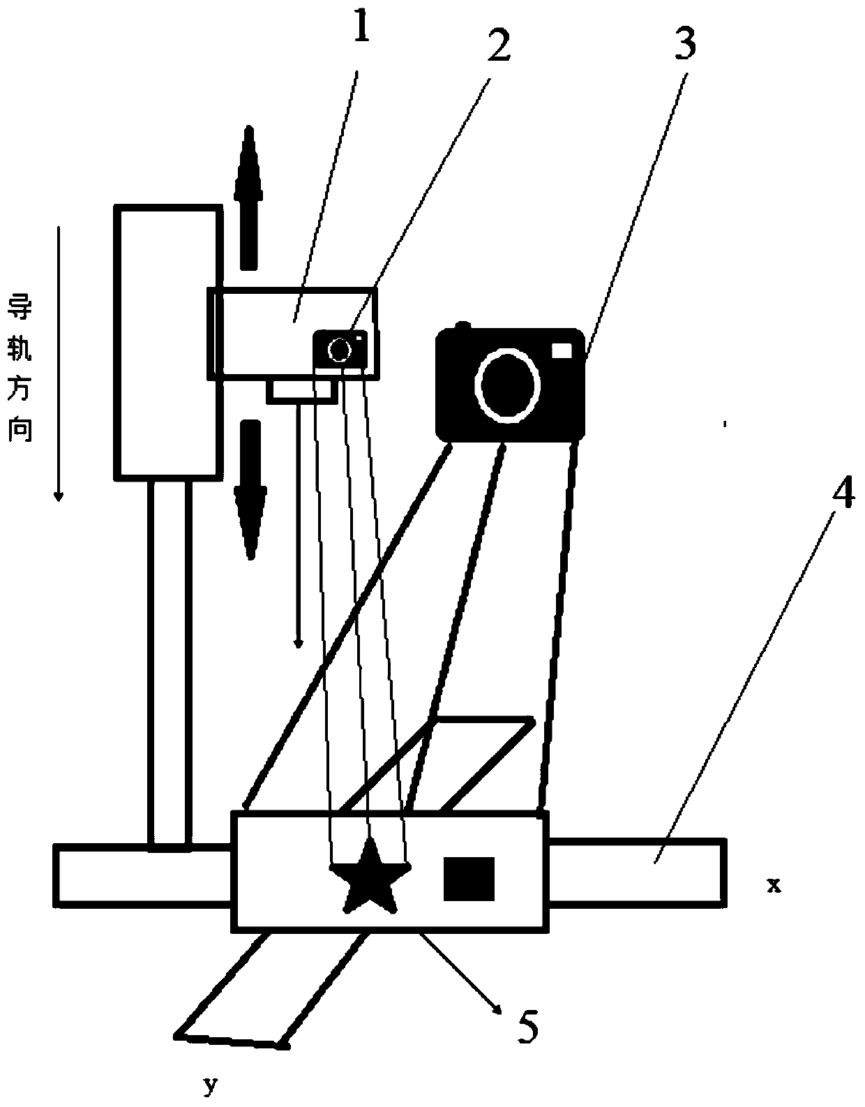
[0040] A laser cutting system based on image recognition according to an embodiment of the present invention includes an image acquisition module, an image processing module, a path planning module, a coordinate calculation module, a laser focus adjustment device 1, a laser cutting unit and a main control unit, the main control unit It is connected with the image acquisition module, the path planning module, the image processing module, the coordinate calculation module and the laser cutting unit.

[0041] Specifically, the image acquisition module includes a first camera 2 and a second camera 3 , and the first camera 2 is used for shooting a panorama of the graphic to be cut from a distance to obtain an overall graphic.

[0042] The image processing module is connected w...


PUM


Abstract

The invention provides a laser cutting system based on image recognition. The system comprises an image acquisition module, an image processing module, a path planning module, a coordinate calculationmodule, a laser cutting unit and a main control unit, wherein the image acquisition module comprises a first camera and a second camera, and the first camera is used for acquiring the integral graphof the graph to be cut; the image processing module is connected with the image acquisition module; the path planning module is connected with the image processing module and is used for dividing thewhole graph acquired by the first camera into a plurality of unit patterns, acquiring the position of each unit pattern and planning the cutting sequence of each unit pattern to acquire the shortest cutting path, and the second camera is used for acquiring the local graph of each unit pattern; the coordinate calculation module is used for calculating coordinate information of the local graphs shotby the second camera after being processed by the image processing module; and the laser cutting unit comprises a laser head and a numerical control objective table. With the system, when multi-target cutting is required for complicated patterns, an optimal cutting path can be obtained, and the required patterns can be obtained through cutting more accurately.

Description

technical field [0001] The invention relates to the technical field of laser processing, in particular to a laser cutting system based on image recognition. Background technique [0002] Although the existing laser cutting control systems on the market can cut various materials, most of them are limited to cutting according to the graphic files derived from the computer. However, in the market, sometimes there are various good-looking printing patterns, but the general CNC cutting system cannot immediately use the computer to generate graphics files in time. [0003] In the field of computer vision, the research history of extracting target contours from source images is not long. People have gradually discovered its important value, and have gradually paid attention to and studied it. Some CNC cutting systems are combined with computer vision technology to recognize graphics, but for complex graphics, for example, there are N patterns in the graphics, it is difficult for s...

Claims


Application Information

Patent Timeline
IPC IPC(8): B23K26/38B23K26/70
CPCB23K26/38B23K26/70B23K26/702
Inventor 叶云霞焦江林肖爱民任旭东任云鹏韩智辉
Owner JIANGSU UNIV
Learn More