Processing fixture for milling plane of upper cover plate

A plane processing and fixture technology, which is applied in the field of top cover milling plane processing fixtures, can solve the problems that the top cover cannot be clamped at the same time, the depth and dimension cannot be guaranteed, and the applicability is poor, and the production cost is reduced, the operation is simple, The effect of improving productivity

Inactive Publication Date: 2019-08-23
HUBEI FANCHAO AUTOMOTIVE IND
View PDF5 Cites 2 Cited by
  • Summary
  • Abstract
  • Description
  • Claims
  • Application Information

AI Technical Summary

Problems solved by technology

This sequence has requirements for the opening depth dimension, but the processing is positioned on the convex surface or the outer arc surface. Due to the deviation of the blank, the depth dimension of different parts of the opening cannot be guaranteed to be consistent.
The existing fixtures for surface milling have poor versatility and cannot satisfy the clamping of the two structures of the upper cover at the same time, and the applicability is poor

Method used


Image

  • Processing fixture for milling plane of upper cover plate
  • Processing fixture for milling plane of upper cover plate
  • Processing fixture for milling plane of upper cover plate

Examples


Embodiment 1

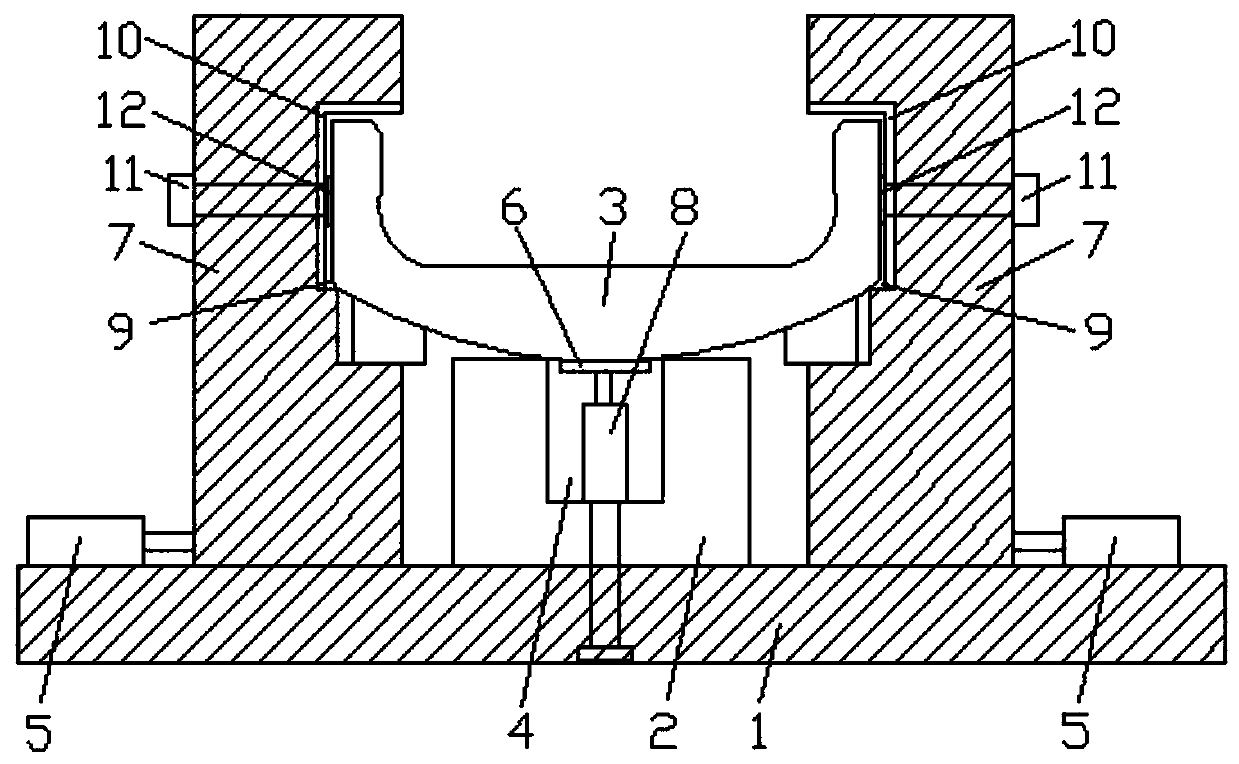
[0039] Such as figure 1 As shown, in this embodiment, each set of clamping assemblies also includes a driving assembly, and the driving assembly includes a horizontally arranged driving cylinder 8. The driving cylinder 8 is arranged on the end of the slide rail away from the upper cover plate 3 and its telescopic end is in contact with the clamping plate. 7 connection (welding), the driving cylinder 8 is welded on one end of the slide rail, which is convenient for disassembly and assembly. When clamping, the horizontal reciprocating movement on the base 1 of the clamping plate 7 is realized by driving the cylinder 8, thereby clamping the upper cover 3 or loosening the upper cover 3, the operation is simple and the degree of automation is high, no manual operation is required, saving Save time and effort.

Embodiment 2

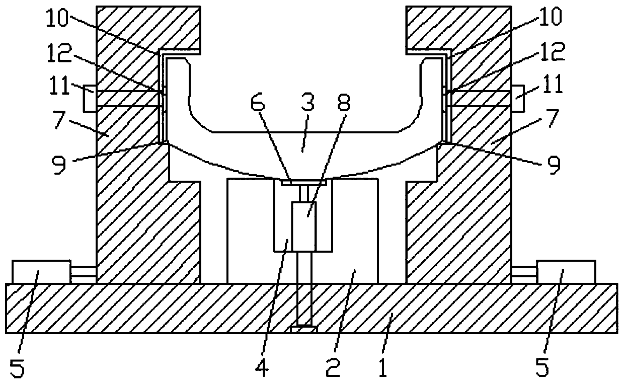
[0041] Such as figure 2As shown, the difference between this embodiment and Embodiment 1 is that the driving assembly includes a motor and a screw rod, and a bar-shaped guide groove is provided on the base 1, and the screw rod is horizontally installed in the guide groove, and one end of the screw rod is connected with the guide groove. One end is rotationally connected, and the other end is welded together with the driving end of the motor installed at the other end of the guide groove; the motor is installed on the other end of the guide groove through welding or bolt connection. A nut is threaded on the screw mandrel, and the slide block on the lower end of the clamping plate 7 is welded together with the nut on the screw mandrel. When clamping, the motor drives the screw to rotate, and the screw converts its own rotation into the linear movement of the nut on it. The two clamping plates move along the corresponding screw with the two nuts and move closer to or farther awa...


PUM


Abstract

The invention relates to a processing fixture for a milling plane of an upper cover plate. The processing fixture for the milling plane of the upper cover plate comprises a base, a support table and two groups of clamping assemblies, wherein the support table is arranged in the center of the base and is used for placing the upper cover plate; the two groups of clamping assemblies are horizontallyand slidably arranged on the base and are symmetrically arranged on two sides of the support table; and the two groups of clamping assemblies are close to each other or away from each other under theaction of an external force so as to clamp or loosen the upper cover plate. The processing fixture for the milling plane of the upper cover plate provided by the invention has the beneficial effects that the requirement on clamping two structures of the upper cover plate can be met at the same time, the applicability is high, the milling plane of the upper cover plate is favorably processed, the production efficiency is improved, and the production cost is reduced.

Description

technical field [0001] The invention relates to the technical field of mechanical processing equipment, in particular to a clamp for milling planes of an upper cover plate. Background technique [0002] The upper cover has two structures, one has a boss on the outer arc surface, and the end surface of the boss has an angle with the inner surface of the upper cover. The upper cover of this structure uses an angled pad when milling the inner surface. The plate supports the boss, so that the inner surface is horizontal, and the widest part on both sides of the workpiece is clamped with flat pliers; the other type has no boss on the outer arc surface, and the upper cover of this structure is supported by a flat backing plate when milling the inner surface. For the outer arc surface, clamp the widest part on both sides of the workpiece with flat-nose pliers. This sequence has requirements for the opening depth dimension, but the machining is positioned on the convex surface or t...

Claims


Application Information

Patent Timeline
IPC IPC(8): B23Q3/08B23Q7/00
CPCB23Q3/062B23Q3/08B23Q7/00B23Q2703/04
Inventor 刘飞孙斌
Owner HUBEI FANCHAO AUTOMOTIVE IND
Why Eureka
Try Eureka