New energy automobile seat with high universality

A new energy vehicle, universal technology, applied in vehicle seats, seat suspension devices, vehicle parts, etc., can solve the problems of no place for garbage, no shoulder and neck massage, no vibration and shock absorption, etc. To achieve the effect of strong versatility, alleviation of collisions, and buffering of collisions

Inactive Publication Date: 2019-08-23
诸暨市领跑管理咨询事务所
0 Cites 7 Cited by

AI-Extracted Technical Summary

Problems solved by technology

[0005] Aiming at the deficiencies of the prior art, the present invention provides a highly versatile new energy vehicle seat, which solves the problem that the vibration is relatively large d...

Abstract

The invention discloses a new energy automobile seat with high universality. An automobile inner floor is included, stainless steel support frames are fixedly connected to the left and right sides onthe automobile inner floor, springs are arranged inside each stainless steel support frame at equal intervals, the left and right sides of the upper end of each stainless steel support frame are provided with bolts, a damping device is connected to the middle of the upper end of the automobile inner floor, and the damping device comprises a first damper platform, aluminum alloy support rods, damping elements and a second damper platform; and the aluminum alloy support rods are welded to the lower end of the first damper platform, the damping elements are arranged in the middles of the aluminumalloy support rods, and the second damper platform is welded to the lower ends of the aluminum alloy support rods. According to the new energy automobile seat with high universality, in the automobile running process, generated vibration can be reduced; and a place where garbage is placed is arranged, and the shoulder and the neck of a driver can be massaged in the driving process.

Application Domain

Seat suspension devices

Technology Topic

EngineeringAluminium alloy +3

Image

  • New energy automobile seat with high universality
  • New energy automobile seat with high universality
  • New energy automobile seat with high universality

Examples

  • Experimental program(1)

Example Embodiment

[0025] The following will clearly and completely describe the technical solutions in the embodiments of the present invention with reference to the accompanying drawings in the embodiments of the present invention. Obviously, the described embodiments are only some of the embodiments of the present invention, not all of them. Based on the embodiments of the present invention, all other embodiments obtained by persons of ordinary skill in the art without making creative efforts belong to the protection scope of the present invention.
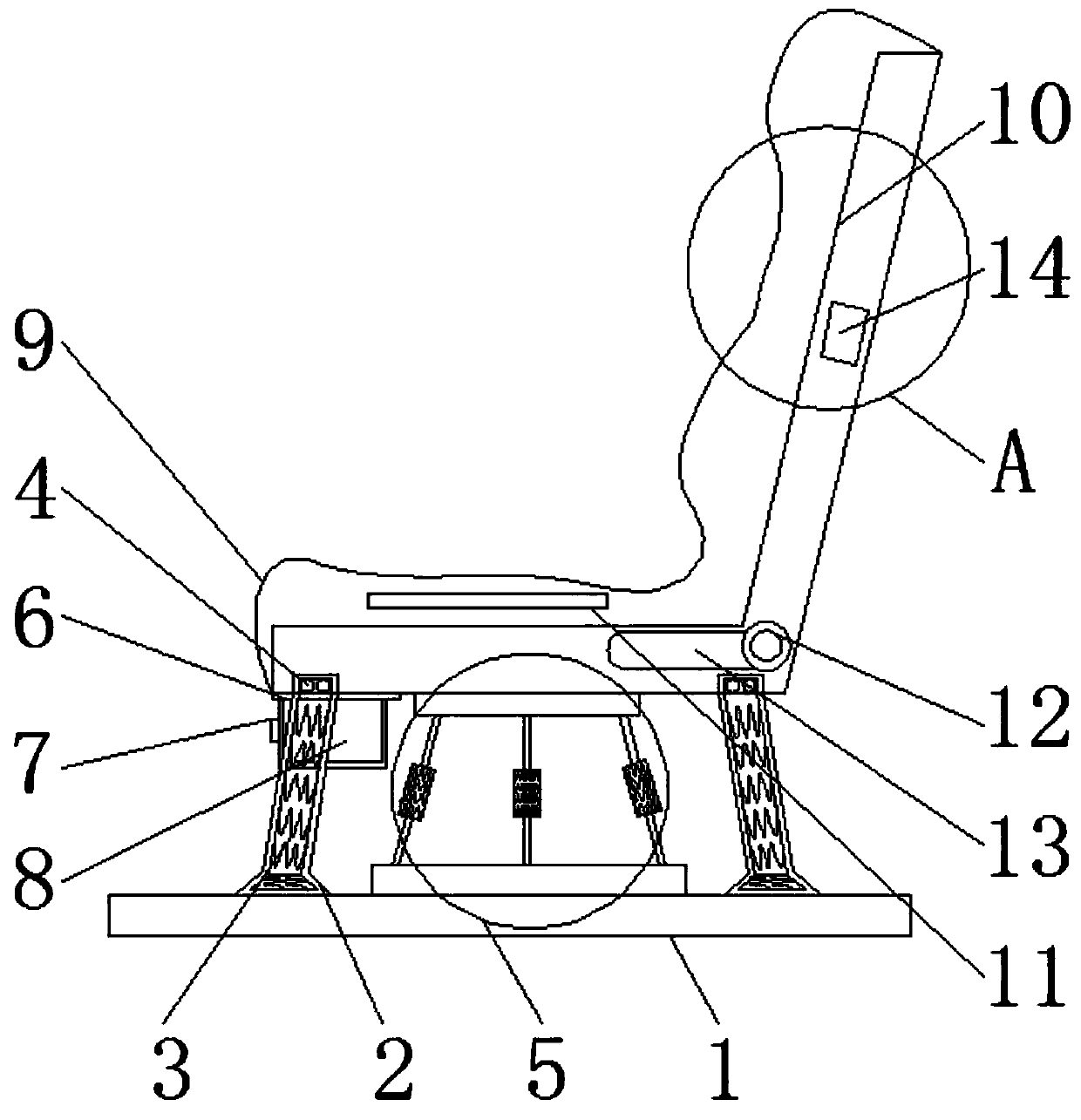
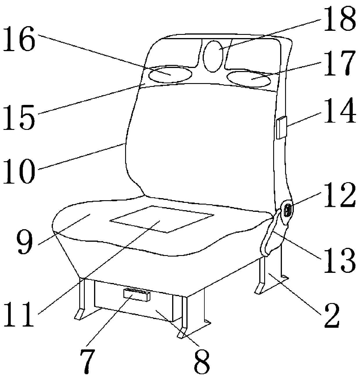
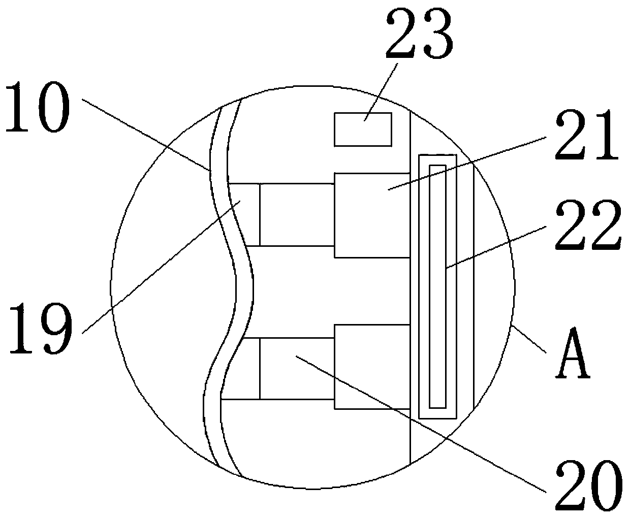
[0026] like Figure 1-4 As shown, the present invention provides a technical solution: a highly versatile new energy car seat, including a car interior floor 1, the upper left and right sides of the car interior floor 1 are fixedly connected with stainless steel support frames 2, The interior of the stainless steel support frame 2 is equidistantly provided with springs 3, and the left and right sides of the upper end of the stainless steel support frame 2 are provided with bolts 4, and the upper end of the automobile inner floor 1 is connected with a damping device 5 in the middle. The shock absorbing device 5 includes a first shock absorbing platform 501, an aluminum alloy support rod 502, a shock absorbing element 503 and a second shock absorbing platform 504, the lower end of the first shock absorbing platform 501 is welded with an aluminum alloy support rod 502, and the The middle of the aluminum alloy support rod 502 is provided with a shock absorbing element 503, the lower end of the aluminum alloy support rod 502 is welded with a second shock absorbing platform 504, the upper end of the shock absorbing device 5 is connected with a cushion 9, and the seat cushion 9 The lower end of the left side is fixedly connected with a chute 6, an auxiliary handle 7 is arranged below the chute 6, a dustbin 8 is welded on the right side of the auxiliary handle 7, and a seat back 10 is fixedly connected with the right end of the seat cushion 9. , the interior of the seat cushion 9 is provided with an airgel plate 11, the front right side of the seat cushion 9 is connected with an anti-slip cylindrical pin 12, and the left side of the anti-slip cylindrical pin 12 is connected with an adjustment handle 13, the seat A controller switch 14 is arranged in the middle of the front of the backrest 10, a rubber gasket 15 is arranged on the outer surface of the upper left side of the seat backrest 10, and a first positioning pad 16 is arranged on the rear outer surface of the rubber gasket 15, The front of the first positioning pad 16 is provided with a second positioning pad 17, the outer surface above the middle of the rubber pad 15 is provided with a third positioning pad 18, and the inner surface of the seat back 10 is connected with a pressure sensor 19. The right end of the pressure sensor 19 is connected with a stainless steel push rod 20, the right end of the stainless steel push rod 20 is provided with an electro-hydraulic rod 21, and a hydraulic cylinder 22 is provided above the stainless steel push rod 20, and the hydraulic cylinder The right side of 22 is provided with central processing unit 23.
[0027] like figure 1 The middle stainless steel support frame 2 is a detachable structure on the seat cushion 9, and the inside of the stainless steel support frame 2 is provided with 7 groups of springs 3 at equal intervals, and the stainless steel support frame 2 is fixed on the car inner floor 1 and the seat cushion 9 at an angle, respectively. The stainless steel support frame 2. Connected to the seat cushion 9 by bolts 4, the stainless steel support frame 2 is a detachable structure on the seat cushion 9, which is convenient for replacing the seat cushion 9. A spring 3 is arranged inside the stainless steel support frame 2, and the spring 3 can relieve the vehicle during driving. The vibration generated, thereby reducing the vibration of the seat, and the stainless steel support frame 2 is tilted and fixed, so that the seat cushion 9 can be more stably fixed on the top of the car interior floor 1, such as Figure 4The first damping platform 501 and the aluminum alloy support rod 502 are welded integrated structures, and the damping element 503 is fixedly connected to the aluminum alloy support rod 502, the damping element 503 is an elastic structure, and the first damping platform 501 The size is smaller than the size of the second damping platform 504, and the second damping platform 504 is the base of the damping device 5, so it is larger than the first damping platform 501, so that the damping device 5 can be installed in the car. The floor 1 is more stable, thereby further stabilizing the cushion 9, preventing the middle part of the cushion 9 from collapsing, and the inside of the damping element 503 is a spring 3, which can reduce the vibration of the seat when the vehicle is running.
[0028] like figure 1 The connection mode between the middle chute 6 and the seat cushion 9 is threaded connection, and the airgel plate 11 runs through the seat cushion 9, and the garbage bin 8 is snapped and connected to the lower end of the seat cushion 9 through the chute 6, and the waste can be used by pulling the auxiliary handle 7 Box 8, the inside of the vehicle is kept clean and tidy through the dustbin 8, the material of the airgel plate 11 is rubber material, and the rubber material is elastic, which can buffer and reduce the vibration generated by the collision, and improve the shock absorption protection effect, such as figure 2 The connection mode between the middle seat back 10 and the rubber gasket 15 is adhesive connection, and the rubber gasket 15 is in an inverted "T" shape structure, and the first positioning pad 16 is fixedly connected to the rubber gasket 15, and the rubber gasket 15 and the rubber gasket 15 are fixedly connected. The first positioning pad 16 is an integrated structure, and massages the driver's shoulders and back of the neck through the first positioning pad 16 , the second positioning pad 17 and the third positioning pad 18 .
[0029] like image 3 The medium pressure sensor 19 is closely attached to the inner surface of the seat back 10, and the connection mode between the seat back 10 and the electro-hydraulic rod 21 is threaded connection, and the connection mode between the stainless steel push rod 20 and the electro-hydraulic rod 21 is welding connection , turn on the hydraulic cylinder 22 and the central processing unit 23 through the controller switch 14, the central processing unit 23 senses each other with the pressure sensor 19 through the central processing unit 23, when the driver leans back on the seat back 10 when driving, the pressure Transmit to the pressure sensor 19, the pressure sensor 19 receives the pressure induction, and transmits the signal to the central processing unit 23, and the central processing unit 23 transmits the instruction to the hydraulic cylinder 22, and then the hydraulic cylinder 22 controls the electro-hydraulic rod 21, so that The electrohydraulic rod 21 extends to the left, thereby driving the stainless steel push rod 20 to push to the left, and then driving the pressure sensor 19 to push to the left. The pressure sensor 19 is located on the first positioning pad 16, the second positioning pad 17 and the third positioning pad 18 Directly behind, the first positioning pad 16, the second positioning pad 17 and the third positioning pad 18 reach the positions required by the driver by pushing the pressure sensor 19, and the hydraulic cylinder 22 transmits instructions to the central processing unit 23, and then the central processing unit 23 The processing device 23 transmits instructions to the pressure sensor 19, and the pressure sensor 19 starts to pressurize the driver's shoulders and the back of the neck after receiving the instructions, so that the driver's shoulders and the back of the neck are supported by force, thereby To achieve the effect of massage.
[0030] During use, the upper end of the floor 1 in the automobile is fixedly connected with a stainless steel support frame 2, and the stainless steel support frame 2 is fixed on the four corners of the lower end of the seat cushion 9 by the bolt 4, and the seat is fixed on the floor 1 of the automobile interior by the stainless steel support frame 2. At the upper end, springs 3 are arranged at equal intervals inside the stainless steel support frame 2, and the vibration generated by the car during driving can be reduced by the spring 3, thereby reducing the vibration of the seat;
[0031] The lower end of the seat cushion 9 is threadedly connected with a shock absorber 5, and the aluminum alloy support rod 502 is welded on the lower end of the first shock absorber platform 501 and the upper end of the second shock absorber platform 504, and is fixedly connected with a shock absorber in the middle of the aluminum alloy support rod 502. Shock element 503, the shock absorber 503 is an elastic structure, through the shock absorber 503 can reduce the vibration brought by the seat during the running of the car, and through the shock absorber 5, the seat can be more stably fixed on the floor 1 of the car The upper end prevents the middle part of the seat from collapsing when the driver sits down;
[0032] Then, the inside of the seat cushion 9 is provided with an airgel plate 11. The airgel plate 11 can buffer and reduce the shock caused by the collision, improve the shock absorption protection effect, and the shock absorption effect of the seat can be reached by the airgel plate 11. Preferably, the upper end of the right side of the seat cushion 9 is fixedly connected with a seat back 10, through which the driver can lean back during the driving process to relieve fatigue, and the right side of the front surface of the seat cushion 9 is provided with an anti-skid Cylindrical pin 12, the outer surface of anti-slip cylindrical pin 12 is coated with anti-skid paint, prevents slipping, and the left side of anti-skid cylindrical pin 12 is connected with adjustment handle 13, by turning anti-skid cylindrical pin 12, then turning upward adjustment handle 13, thereby adjusting the seat the position of the backrest 10;
[0033] Above the left side outer surface of the seat back 10, a rubber gasket 15 is arranged, and on the outer surface of the rubber gasket 15, a first positioning pad 16 and a second positioning pad 17 are arranged. The outer surface above the middle of the pad 17 is provided with a third positioning pad 18, the central processing unit 23 is opened by the controller switch 14, the pressure sensor 19 receives the pressure induction, and the signal is transmitted to the central processing unit 23, and the central processing unit 23 transmits Command to the hydraulic cylinder 22, and then the hydraulic cylinder 22 controls the electro-hydraulic rod 21, so that the electro-hydraulic rod 21 extends to the left, thereby driving the stainless steel push rod 20 to push to the left, and then driving the pressure sensor 19 to push to the left, and the pressure sensor 19 Located directly behind the first positioning pad 16, the second positioning pad 17 and the third positioning pad 18, by pushing the pressure sensor 19, the first positioning pad 16, the second positioning pad 17 and the third positioning pad 18 reach the position of the driver. For the required position, the hydraulic cylinder 22 transmits the command to the central processing unit 23, and then the central processing unit 23 transmits the command to the pressure sensor 19, and the pressure sensor 19 starts to pressurize the driver’s shoulders and back of the neck after receiving the command , so that the driver's shoulders and the back of the neck receive strong support, so as to achieve the effect of massage.
[0034] In summary, 1. The highly versatile seat for new energy vehicles is provided with springs 3 and shock absorbing devices 5, and springs 3 are arranged at equal intervals inside the stainless steel support frame 2, and the vehicle can be lightened by the springs 3. For the vibration brought to the seat during driving, a shock absorber 5 is arranged below the seat cushion 9, and the aluminum alloy support rod 502 is moved by the first shock absorber platform 501 and the second shock absorber platform 504 in the shock absorber 5. It is fixed in the middle of the two, and a shock absorbing element 503 is arranged in the middle of the aluminum alloy support rod 502. The shock absorbing element 503 reduces the vibration brought to the seat when the car is running, and the shock absorbing effect is improved by the spring 3 and the shock absorbing element 503. Be at your best.
[0035] 2. The highly versatile seat for new energy vehicles is provided with a chute 6, a dustbin 8 and an airgel plate 11, and a chute 6 is provided at the lower end of the seat cushion 9, and the edge of the chute 6 has a block , the garbage bin 8 is fixed on the chute 6 through the clamping block to slide, and the garbage bin 8 is pulled out from the bottom of the seat cushion 9 through the auxiliary handle 7, which is convenient for the driver to place garbage during driving and keeps the car clean. The airgel plate 11 is arranged inside, and the airgel plate 11 has the function of buffering and reducing collisions, and the shock absorption and protection effect can be improved through the airgel plate 11 .
[0036] 3. The highly versatile seat for new energy vehicles is provided with a first positioning pad 16, a second positioning pad 17 and a third positioning pad 18, and a second positioning pad is provided on the rear side of the upper left surface of the seat back 10. A positioning pad 16 is provided with a second positioning pad 17 in front of the first positioning pad 16, and a third positioning pad 18 is arranged in the middle of the upper left side of the seat back 10, by first positioning pad 16 and the second positioning pad Pad 17 is pushed to the driver's left and right shoulder position, thereby reaches the required position of driver, reaches the effect of massage, by pushing the third positioning pad 18 to the back neck position of driver, thereby reaches the effect of massage neck.
[0037] 4. The highly versatile new energy vehicle seat is provided with a controller switch 14, a pressure sensor 19, a stainless steel push rod 20, an electro-hydraulic rod 21, a hydraulic cylinder 22 and a central processing unit 23, and the backrest of the seat 10 is provided with a controller switch 14 in the middle of the front side, and a pressure sensor 19, a stainless steel push rod 20, an electro-hydraulic rod 21, a hydraulic cylinder 22 and a central processing unit 23 are arranged inside the seat back 10. Open the hydraulic cylinder 22 and the central processing unit 23, then the hydraulic cylinder 22 transmits instructions to the electro-hydraulic rod 21, and then the electro-hydraulic rod 21 begins to extend to the left, thereby pushing the stainless steel push rod 20 to the left, and the central processing unit 23 transmits instructions to Pressure sensor 19, then turn on the pressure sensor 19, when the driver is driving, lean back on the seat back 10, and then transmit the pressure to the pressure sensor 19, and the pressure signal will be transmitted to the center through the pressure sensor 19 On the processing device 23, the central processing device 23 transmits instructions to the hydraulic cylinder 22, and then the hydraulic cylinder 22 drives the electro-hydraulic rod 21 to start extending to the left, so that the stainless steel push rod 20 is pushed to the left, and then the first positioning pad 16, The second positioning pad 17 and the third positioning pad 18 are pushed to the driver's desired position, so that the driver's shoulders and neck are supported by force, thereby achieving the effect of comfort and massage.
[0038] Although the embodiments of the present invention have been shown and described, those skilled in the art can understand that various changes, modifications and substitutions can be made to these embodiments without departing from the principle and spirit of the present invention. and modifications, the scope of the invention is defined by the appended claims and their equivalents.

PUM

no PUM

Description & Claims & Application Information

We can also present the details of the Description, Claims and Application information to help users get a comprehensive understanding of the technical details of the patent, such as background art, summary of invention, brief description of drawings, description of embodiments, and other original content. On the other hand, users can also determine the specific scope of protection of the technology through the list of claims; as well as understand the changes in the life cycle of the technology with the presentation of the patent timeline. Login to view more.

Similar technology patents

Intelligent shoe system

ActiveCN105342617Aeasy to useVersatile
Owner:西安赛狮鞋业有限公司

Transport vehicle capable of climbing cylinders

InactiveCN104163215Asimple materialVersatile
Owner:SOUTHEAST UNIV

Classification and recommendation of technical efficacy words

  • Versatile
  • reduce collision

Automobile electric control unit calibration system and method based on ASAP standard

InactiveCN101334662AVersatileResolve interface mismatch
Owner:CHONGQING UNIV OF POSTS & TELECOMM

Multi-bus automobile communication control module based on TCN

ActiveCN1889494AaccelerateVersatile
Owner:ZHUZHOU CSR TIMES ELECTRIC CO LTD

Double on-site bus interface converter

InactiveCN101345629AStrong flexibilityVersatile
Owner:WUHAN UNIV OF SCI & TECH

Enterprise collaborative office management system

InactiveCN105139181AVersatileeasy to operate
Owner:SUZHOU LANGJIETONG INTELLIGENT TECH
Why Eureka
Try Eureka