
Rear spoiler apparatus for vehicle

A spoiler and equipment technology, applied in the direction of vehicle components, body, body stability, etc., can solve problems such as drivability degradation, tire grip reduction, accidents, etc., to achieve maximum driving stability, reduce lift, reduce Effects of Manufacturing Cost and Weight

Active Publication Date: 2019-08-23
HYUNDAI MOTOR CO LTD +1
View PDF6 Cites 5 Cited by
  • Summary
  • Abstract
  • Description
  • Claims
  • Application Information

AI Technical Summary

Problems solved by technology

[0002] While driving the vehicle, the body tends to lift as the speed of the vehicle increases, and in this case, the grip of the tires decreases, so that drivability deteriorates, and if severe, it can lead to accidents

Method used


Image

  • Rear spoiler apparatus for vehicle
  • Rear spoiler apparatus for vehicle
  • Rear spoiler apparatus for vehicle

Examples


Embodiment Construction

[0031] Reference will now be made in detail to various embodiments of the invention, examples of which are illustrated in the accompanying drawings and described below. While the invention will be described in conjunction with representative embodiments, it will be understood that present description is not intended to limit the invention to those representative embodiments. On the contrary, the invention is intended to cover not only these representative embodiments, but also various alternatives, modifications, equivalents and other embodiments, which may be included in the scope of the present invention as defined by the appended claims. within the spirit and scope of the invention as defined by the claims.

[0032] Hereinafter, a rear spoiler apparatus for a vehicle according to a representative embodiment of the present invention is described in detail with reference to the accompanying drawings.

[0033] A rear spoiler apparatus for a vehicle according to a representati...


PUM


Abstract

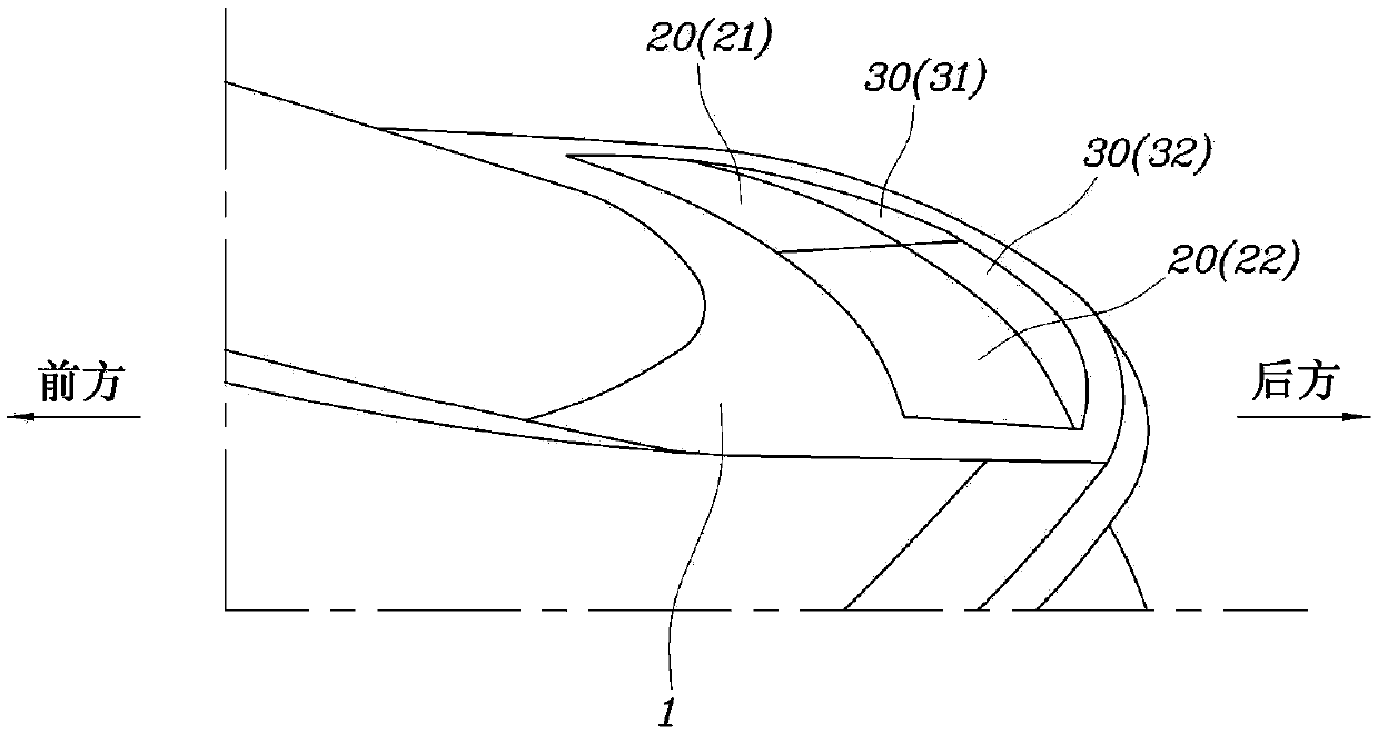
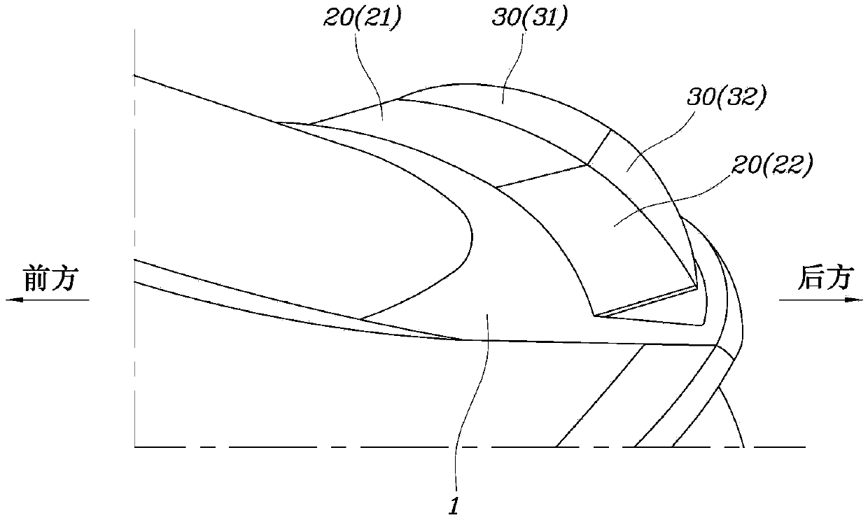
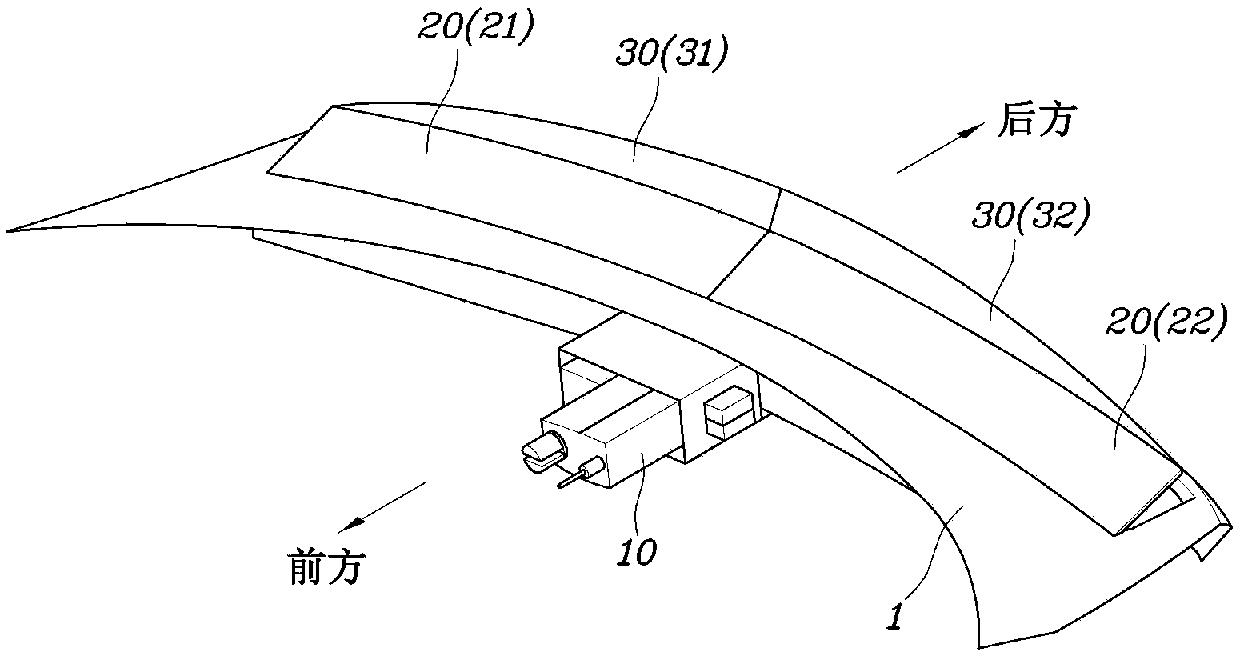
A rear spoiler apparatus for a vehicle may include a main flap which is deployed by an operation force from an actuator and a support flap which is additionally deployed from the main flap, in which the support flap rotates to open together when the main flap rotates and the open angle of the support flap is greater than the open angle of the support flap.

Description

technical field [0001] The present invention relates to a rear spoiler device for a vehicle, and more particularly, to a rear spoiler device for a vehicle having a main flap (flap) operated by an actuator. ) and a support flap operating in conjunction with the main flap. Background technique [0002] While driving the vehicle, the vehicle body tends to lift as the speed of the vehicle increases, and in this case, the grip of the tires decreases, so that drivability deteriorates, and if serious, it causes an accident. [0003] In order to prevent this problem, a spoiler is installed on the vehicle, which is an accessory that uses airflow to press down on the vehicle body when the vehicle is driven. A spoiler is also called an air spoiler because it changes the airflow. [0004] More recently, a spoiler arrangement has additional support flaps that are deployed in addition to the main flap that is deployed to minimize lift. In the configuration of additionally deploying the...

Claims


Application Information

Patent Timeline
Patent Type & Authority Applications(China)
IPC IPC(8): B62D35/00
CPCB62D35/007B62D37/02Y02T10/82B62D25/10
Inventor 金学林郑民植朴相炫黄义昌金昇焕李东国姜求哲
Owner HYUNDAI MOTOR CO LTD
Learn More