Supercharge Your Innovation With Domain-Expert AI Agents!

Ocean remote sensing detecting device

A detection device and ocean remote sensing technology, which is applied in the direction of mechanical gear transmission, rotary propeller, rotating propeller, etc., can solve the problems that the propeller cannot flexibly adjust the propulsion force, the propeller is not fixed firmly, and the propeller damages the propulsion force. The force is adjustable and flexible, the speed change is efficient and fast, and the travel time is shortened

Active Publication Date: 2019-08-23
重庆奥普提科技有限公司
View PDF9 Cites 0 Cited by
  • Summary
  • Abstract
  • Description
  • Claims
  • Application Information

AI Technical Summary

Problems solved by technology

[0002] With the increasing pollution of the marine environment, some marine remote sensing detection devices are used more and more widely. Marine remote sensing detection devices are usually driven by propellers. The current propellers are divided into two types: fixed pitch propellers and variable pitch propellers. Changing the pitch changes the propulsion force and is widely used. For the current variable pitch propeller, its structure is complex, and the process of changing the pitch is prone to connection failure due to the complexity and multi-coordination between the structures. The stability of the propeller is poor during the process of pitch change, and it is prone to bending when it is subjected to a large pressure, and the propeller after the pitch change is prone to problems of loose fixation, resulting in damage to the propeller and a decrease in propulsion; secondly, the existing The propeller cannot flexibly adjust the propulsion while changing the direction of the hull, and its function is simple

Method used


Image

  • Ocean remote sensing detecting device
  • Ocean remote sensing detecting device
  • Ocean remote sensing detecting device

Examples


Embodiment Construction

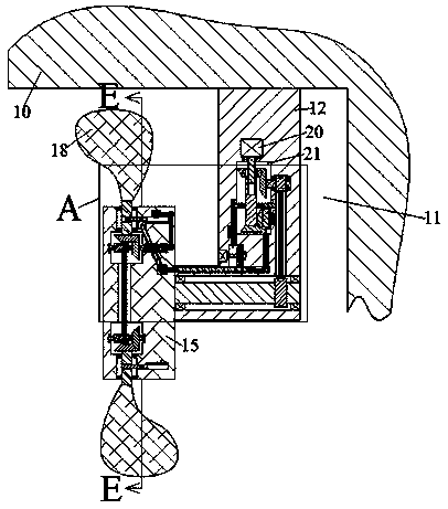
[0018] Combine below Figure 1-7 The present invention is described in detail, and for convenience of description, the orientations mentioned below are now stipulated as follows: figure 1 The up, down, left, right, front and back directions of the projection relationship itself are the same.

[0019] refer to Figure 1-7 , according to an embodiment of the present invention, a marine remote sensing detection device includes a hull 10 with the bow facing right, and a propulsion chamber 11 with an opening facing left and the lower side communicating with the outside world is provided in the hull 10, the propulsion chamber 11 The upper end wall is fixed with a fixed block 12, the fixed block 12 is provided with a power device, and the lower side of the power device is provided with a rotating groove 13 with an opening left and right in the fixed block 12, and the rotating groove 13 passes through Bearing rotation is provided with rotating shaft 14, and described rotating shaft ...


PUM


Abstract

The invention discloses an ocean remote sensing detecting device which comprises a ship body with a rightward ship head. A pushing cavity provided with a leftward opening is formed in the ship body, the lower side of the pushing cavity communicates with the outside, the upper end wall of the pushing cavity is fixedly provided with a fixing block, a power device is arranged in the fixing block, a rotating slot with an opening which is through left and right is formed in the fixing block and in the lower side of the power device, and a rotating shaft is rotationally arranged in the rotating slotthrough a bearing. The ocean remote sensing detecting device is simple in structure and convenient to operate; the power device is used for enabling a propeller to rotate so as to push the ship bodyto go forwards, and the direction of the pushing force changes the heading of the ship body. When the speed is required to be decreased or the draw alongside distance of the ship body is required to be shortened, the propeller is rotated by a half circle so as to enable the pushing force during rotation to be a negative value, the ship body is decelerated under the action of resistance when goingforwards, the travel time of deceleration is shortened, the pushing force of the pushing device is adjustable and flexible, meanwhile, the heading of the ship body can be changed, speed changing is efficient and rapid, energy consumption is low, and use is facilitated.

Description

technical field [0001] The invention relates to the technical field of marine environment detection, in particular to a marine remote sensing detection device. Background technique [0002] With the increasing pollution of the marine environment, some marine remote sensing detection devices are used more and more widely. Marine remote sensing detection devices are usually driven by propellers. The current propellers are divided into two types: fixed pitch propellers and variable pitch propellers. Changing the pitch changes the propulsion force and is widely used. For the current variable pitch propeller, its structure is complex, and the process of changing the pitch is prone to connection failure due to the complexity and multi-coordination between the structures. The stability of the propeller is poor during the process of pitch change, and it is prone to bending when it is subjected to a large pressure, and the propeller after the pitch change is prone to problems of loos...

Claims


Application Information

Patent Timeline
Patent Type & Authority Applications(China)
IPC IPC(8): B63H1/14B63H23/10
CPCB63H1/14B63H23/10
Inventor 李凤鸣
Owner 重庆奥普提科技有限公司
Features
  • R&D
  • Intellectual Property
  • Life Sciences
  • Materials
  • Tech Scout
  • Unparalleled Data Quality
  • Higher Quality Content
  • 60% Fewer Hallucinations
Learn More