
Space debris protection structure

A technology for protecting structures and space debris, applied in aerospace safety/emergency devices, etc., can solve problems such as inability to use for a long time, reduced structural strength, and inability to meet the requirements of debris protection with larger diameters

Active Publication Date: 2019-08-23
BEIJING RES INST OF MECHANICAL & ELECTRICAL TECH
View PDF8 Cites 6 Cited by
  • Summary
  • Abstract
  • Description
  • Claims
  • Application Information

AI Technical Summary

Problems solved by technology

Existing protective structures mostly adopt single-layer or multi-layer protective screen structures, such as patent applications CN105109709 and CN107140238. Although this type of protective structure can absorb and disperse space debris to a certain extent, on the one hand, due to the four All the boundaries are in a free state. Under the high-speed impact of space debris, more stress will be generated, and the scattering of the boundary will lead to a large stress concentration, which will reduce the structural strength of this type of structure and cannot be used for a long time; on the other hand, limited to The structural form (plate shape) of this type of structure makes it impossible to fully protect the cabin; moreover, the critical diameter of the projectile measured by these protective structure schemes stays at the millimeter level, which cannot meet the protection requirements for fragments with larger diameters

Method used


Image

  • Space debris protection structure
  • Space debris protection structure

Examples


Embodiment Construction

[0022] It should be noted that, in the case of no conflict, the embodiments in the present application and the features in the embodiments can be combined with each other. The following will clearly and completely describe the technical solutions in the embodiments of the present invention with reference to the accompanying drawings in the embodiments of the present invention. Obviously, the described embodiments are only some, not all, embodiments of the present invention. The following description of at least one exemplary embodiment is merely illustrative in nature and in no way taken as limiting the invention, its application or uses. Based on the embodiments of the present invention, all other embodiments obtained by persons of ordinary skill in the art without creative efforts fall within the protection scope of the present invention.

[0023] It should be noted that the terminology used here is only for describing specific implementations, and is not intended to limit t...


PUM


Abstract

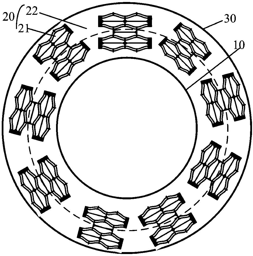
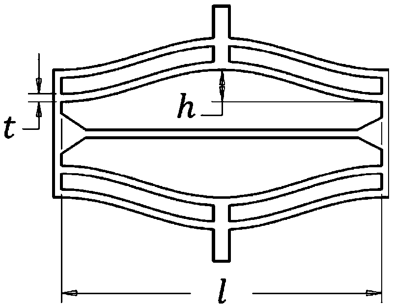
The embodiment of the invention provides a space debris protection structure. The protection structure comprises an inner supporting layer, an intermediate layer and an outer protection layer. The inner supporting layer is used for fixing the intermediate layer and provided with a cavity with two open ends, and the cavity is used for accommodating a to-be-protected piece; the intermediate layer isarranged between the inner supporting layer and the outer protection layer and at least composed of cellular structures, the cellular structures are circumferentially arranged on the outer surface ofthe inner supporting layer, and the intermediate layer is at least used for absorbing energy of space debris; and the outer protection layer is circumferentially arranged on the outer surface of theintermediate layer, a smooth transition layer is further arranged on the outer surface of the outer protection layer, and the outer protection layer is used for crushing the space debris. By means ofthe space debris protection structure provided by the embodiment of the invention, the technical problems that an existing space debris protection structure is large in stress concentration, fails toprotect a space cabin comprehensively and fails to meet larger-diameter debris protection requirements can be solved.

Description

technical field [0001] The invention provides a space debris protection structure, in particular relates to a Whipple type high-performance space debris protection structure, which belongs to the technical field of space debris protection. Background technique [0002] Many spacecraft orbiting the earth play an extremely important role in scientific research, positioning and navigation, communication relay, and national security. However, during the operation of the spacecraft, the safety of the spacecraft is seriously threatened by the small particles of alumina after the combustion of the solid rocket motor and the space debris as large as the last stage of the launch vehicle. When space debris moving at super high speed hits a spacecraft, it will cause craters, perforations, and even catastrophic damage to the spacecraft, and will lead to the generation of more space junk. At present, for large space debris with a diameter of about 10 cm or more, the international commun...

Claims


Application Information

Patent Timeline
Patent Type & Authority Applications(China)
IPC IPC(8): B64G1/52
CPCB64G1/52
Inventor 肖登红高勇张苏李小婷周小红仝宗凯
Owner BEIJING RES INST OF MECHANICAL & ELECTRICAL TECH
Learn More